Bench Degree·REFRIGERATIONchapter

Chapter 21: Reading a Real Installation
Three machines in one room, and every idea in this book applied to them. If you can walk into this room and say what each unit will do, refuse to do, and never tell you about, the book has done its job.
Twenty chapters of groundwork exist for this one. Here is the test promised in Chapter 1, and here is the room.
An office suite in Massachusetts with a server room in it. Three supplemental air conditioners, sized to hold that room while the building’s main system does whatever it does:
- Two identical Trane Odyssey TTA split systems. Twenty tons each, 240,000 Btu/h (70.3 kW) between them. Three-phase. 33 RLA compressors.
- One much older York unit, on a plain mechanical thermostat.
The two Tranes are controlled as a lead/lag pair. The York is not controlled by anything except its own thermostat.
By the end of this chapter you should be able to say why every one of those decisions is defensible, what the equipment will refuse to do, and why nobody can wire an alarm to it.
Section 1: What the Nameplate Says, Field by Field
Start where a technician starts. Every field, and what each one buys you.
Model designation. Trane’s Odyssey nomenclature encodes capacity in the model number, in units of 1,000 Btu/h (293 W). A TTA240 is 240,000 Btu/h (70.3 kW) nominal, a TTA120 is 120,000 Btu/h (35.2 kW). Two units of 120 each, or 20 tons apiece, gives the 240,000 Btu/h (70.3 kW) total.
“Split system” matters. TTA is the outdoor condensing section. There is a matching indoor air handler and a line set between them, which means everything in Chapter 18 applies: line sizing, oil return on vertical risers, suction line insulation, and charge adjustment for line length. On a 20-ton machine those line sets are large and long, and the charge adjustment is not a rounding error.
Refrigerant and charge weight. Odyssey units of this vintage are R-410A. Chapter 8 gives the consequences: POE oil, therefore hygroscopic, therefore the drier is replaced whenever the system is opened and the system is not left open. And a GWP of 2,088, so a leak is both expensive and reportable above certain quantities.
Voltage and phase. Three phase, and the specific system matters. In a US commercial building this will be either 208 V or 460 V, and Chapter 20 Section 1 explains why those are different machines rather than a range.
RLA 33 A per compressor. This is the number a clamp meter is compared against, and it is the number the monitoring in Section 6 is built on.
LRA. Not quoted above but on the plate, and at Chapter 20’s typical five to eight times RLA it will be 165 to 265 A per compressor. That figure decides the starting method and explains why the disconnect and contactors are the size they are.
MCA and MOCP. Chapter 20 Section 2. Wire to MCA, protect to no more than MOCP, and expect the breaker to look oversized relative to the conductor. On a machine this size the MCA will be well over 100 A.
Number of refrigerant circuits. A 20-ton unit is very likely two circuits with two compressors, interleaved through one coil. Which means the machine has internal staging of its own, independent of the lead/lag control between the two units. Section 4 comes back to this because it changes what “one unit running” means.
SLOW DOWN. Check Your Understanding: A clamp meter on one compressor leg of a running TTA120 reads 21 A against an RLA of 33 A. Is the machine faulty, undercharged, or fine? Think before reading on.
Most likely fine, and probably running at part load or in mild weather. RLA is the current at rated conditions, which means design outdoor temperature and full load. On a cool day the condensing pressure is lower, so the compressor works across a smaller lift, so it draws less current. Current tracks head pressure. A reading well below RLA on a mild day is expected; a reading below RLA on a design-condition afternoon suggests low charge or a compressor not pumping. Always ask what the conditions were, which is why Chapter 12 insisted on steady state and why a logged reading beats a spot reading.
Section 2: What It Will Deliver on a Hot Afternoon
The question from Chapter 1: what will this machine actually do at 35 °C (95 °F)?
Not 240,000 Btu/h. Nameplate capacity is quoted at standard rating conditions, and real capacity varies with both the outdoor air temperature and the indoor conditions.
Outdoor temperature reduces capacity. Hotter outdoor air means a higher condensing temperature, which by Chapter 13’s argument means a larger pressure lift, more compressor work and less net cooling. Expect roughly 1 to 2 percent capacity loss per °C (0.5 to 1 percent per °F) above the rating point. At 41 °C (105 °F) rather than 35 °C (95 °F), expect 6 to 12 percent less.
Indoor conditions change both the amount and the character. Chapter 14: capacity is split between sensible and latent according to the sensible heat ratio, and a server room’s SHR approaches 1.0.
And that is the good news. In a house, a nominal 20-ton machine at SHR 0.75 delivers about 15 tons of temperature change and spends the rest condensing water. In this room, with essentially no latent load, nearly all 20 tons is available as sensible cooling. The manufacturer’s expanded performance data will show a higher total and a much higher sensible capacity at low entering wet-bulb, and that is the table to use rather than the nameplate.
Which also means, from Chapter 14 Section 8, that the coil can be allowed to run warmer. There is no reason to hold an evaporator at 4 °C (40 °F) to wring out moisture that is not present. A higher evaporating temperature raises COP directly.
And the load is constant. A house peaks in late afternoon and falls overnight. This room’s load is the rack draw, which is the same at 4 a.m. as at 4 p.m. No diversity, no peak, no coasting. Chapter 15 Section 7: measure the electrical draw of the racks, add ten to twenty percent, and that is the load.
Section 3: What It Will Refuse To Do, and Why
The second question from Chapter 1: what happens at 4 °C (40 °F) outdoor?
As built, these units stop at about 10 °C (50 °F) outdoor air temperature. Below that they will trip, short-cycle, or refuse to start.
This is not a defect and it is not a setting. It is Chapter 20 Section 6’s low ambient problem, and it is worth restating because it is the single most counterintuitive fact about commercial cooling equipment.
As outdoor air gets colder the condenser rejects heat too easily. Condensing pressure falls. Chapter 7’s saturation curve then works against you: the pressure difference across the metering device collapses, so refrigerant flow drops, the evaporator starves, suction pressure falls, and the low pressure cutout opens. The machine has failed because it is too cold outside.
For most air conditioning that never matters, because nobody cools a house in January. For a server room it matters enormously, because the load does not care what season it is. This room needs cooling on the coldest night of the year.
The fix is a head-pressure control kit, which for this equipment family is the BAYLOAMS10* low-ambient option. It works by the third method in Chapter 20 Section 6: controlling condenser fan operation, and in the fuller implementations flooding the condenser to reduce its active surface, so head pressure is held up artificially when the weather will not do it.
Three things worth being clear about:
It is a physical kit, not a configuration change. No amount of adjusting setpoints substitutes for it.
It must be specified for the actual minimum operating temperature required, not merely “winter”. A kit good to minus 7 °C (20 °F) does not help on a night at minus 18 °C (0 °F).
And in a New England climate this is not an edge case. Outdoor temperatures below 10 °C (50 °F) occur for a substantial part of the year. A server room cooled by unmodified equipment is a server room with no cooling for several months, unless something else is carrying the load, which is worth establishing rather than assuming.
Section 4: Why Two Units and Not One
The third question. Two 20-ton machines rather than one 40-ton machine, and the reasons are all good ones.
Redundancy, which is the main one. A server room losing cooling is a room with a clock running on it. Two machines mean one can fail and the room survives, degraded. One large machine means a single point of failure on the thing protecting everything else in the building.
Staging and part-load efficiency. Chapter 20 Section 5 and Chapter 14 Section 7 both argue against a machine that only knows full output. Two units give at least two steps, and with two circuits each, potentially four. On a mild night one compressor on one unit may carry the whole load, running long steady cycles, which is exactly what you want.
Avoiding short cycling. A 40-ton machine on a 15-ton load would satisfy in minutes and stop. Chapter 14 explains what that costs in a house; in a server room it costs compressor life, because starts are what wear a compressor rather than running hours.
Even wear. Which is what lead/lag control is actually for.
And physical practicality. Two 20-ton units can be craned onto a roof and fit through the plant room; one 40-ton machine may not.
Section 5: How Lead/Lag Actually Decides
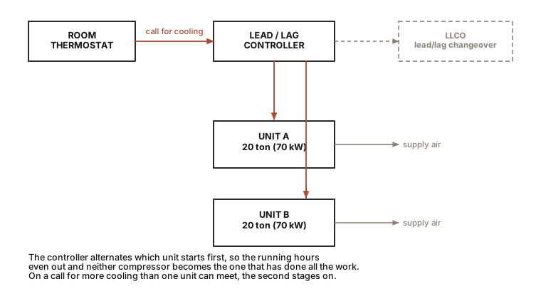
A lead/lag controller sits between the thermostat and the two units and answers two questions: which unit starts first, and when does the second one join.
Staging on demand. As the room rises above setpoint, the lead unit starts. If the temperature keeps rising past a second, higher setpoint, the lag unit starts too. Coming down, the lag drops out first. Both stages have their own differential so neither hunts.
Rotation. The controller swaps which unit is lead, on a schedule of days or on accumulated run hours. Without rotation one compressor accumulates every hour and the other sits idle, and an idle compressor in a cold plant room is at risk from the refrigerant migration of Chapter 20 Section 6, quite apart from the wear imbalance.
Failure fallback. If the lead unit fails to satisfy, the controller promotes the lag unit. This is the part that makes redundancy real rather than theoretical, and it is worth testing rather than trusting.
Minimum off time, typically three to five minutes, and minimum run time. Both exist to protect the compressor from rapid cycling, and the minimum off time also lets system pressures equalise so the next start is not against full head pressure.
The specific controller selected for this installation is a
Bard MC4002-BC, which has an LLCO lead/lag
changeover terminal and treats Stage 2 as the lag unit.
It was chosen for a practical reason worth recording: it is an orderable
product rather than a category. The alternative considered was
quote-only, and a controller you can buy today beats a marginally better
one you can request a price for.
One design note about the pair. Because each unit may itself have two refrigerant circuits, the real staging tree is deeper than “unit 1, unit 2”. A well-commissioned installation proves every stage, and a badly commissioned one runs happily on stage one for a year while stage three has never worked. Chapter 20’s field checklist item 9 exists for exactly this, and it is the commonest hidden fault on multi-stage equipment.
Section 6: Why You Cannot Wire an Alarm, and What To Do Instead
The fourth question from Chapter 1, and the one with the most practical consequence.
These units expose no fault output contact. Not because it was omitted to save money, but because of the design decision in Chapter 20 Section 7: every protective device on the machine is auto-reset.
HPCO, LPCO, DTL, IOL and EDC all open the control circuit, the machine stops, the condition clears, they close, and it restarts. No latch, no memory, no indicating flag, and nothing brought out to a terminal.
So a unit that tripped on high pressure at 2 a.m. and restarted four minutes later is, at 8 a.m., indistinguishable from a unit that ran all night without incident. There is no fault to alarm on because the machine does not consider it a fault.
The workaround is to monitor behaviour rather than status, and the signal is short cycling.
Clamp a current transformer around one compressor leg on each unit and log it. That is the entire instrumentation, and it yields:
- Run time per cycle, which is the health indicator.
- Starts per hour.
- Current magnitude, comparable against the 33 A RLA, which tracks head pressure and therefore load and condenser condition.
- Confirmation that each stage actually runs, which addresses the hidden-stage problem of Section 5.
The alarm rule that works:
Alarm if compressor run time is under five minutes, or if starts exceed six per hour, under steady load.
That is not a fault signal. It is an inference, and on equipment that reports nothing about itself it is the only reliable option.
Two practical notes on the CT. The trip point must suit the actual compressor: 33 RLA compressors need a CT set to trip around 15 to 20 A, not the 8 to 12 A that would suit a residential machine, so that the sensor reliably distinguishes running from stopped without chattering. And it must be a three-phase-appropriate installation: a single-phase energy meter cannot be used on a three-phase load, which is a mistake worth avoiding at the specification stage rather than after delivery.
Beyond current, three more signals are cheap and worth having:
Room temperature, logged, with an alarm at a threshold and a second alarm on rate of rise. Rate of rise is the better signal, because it detects loss of cooling long before the absolute temperature becomes dangerous, and it is proportional to how much load is unmatched.
Condensate flow or presence, which in a low-latent room is nearly zero, so its appearance means outdoor air is infiltrating.
Power to the whole panel, so a tripped breaker is distinguishable from a machine choosing not to run.
Section 7: The Old York, and Why It Is Not Neglect
The third machine, on a plain mechanical thermostat, with no controller, no monitoring and no integration.
That is a defensible engineering choice, and understanding why is a good test of whether the rest of this book has landed.
It is the backstop, not part of the sequence. Its job is to be a third machine that works when the pair does not. Adding it to the lead/lag control would make it depend on the same controller, the same wiring and the same logic as the units it exists to back up. A backstop that shares a failure mode with the primary is not a backstop.
A capillary bulb thermostat is extremely reliable. Chapter 17 Section 3: a sealed tube of volatile fluid, a snap switch, no electronics and no power. That is Chapter 7’s saturation curve used as a sensor, and it has a failure rate that shames anything with a circuit board in it.
It cannot be misconfigured, because there is nothing to configure. No firmware, no setpoint drift, no dead controller battery, and nobody can leave it in a service mode.
And its inefficiency is nearly irrelevant if it runs rarely. An older machine may be substantially less efficient than the Tranes, and that matters only in proportion to run hours. A unit that runs a few hours a month costs almost nothing in energy and is worth a great deal in availability.
IN PLAIN ENGLISH: The two new machines are the system. The old one is the parachute. You do not connect a parachute to the aeroplane’s flight computer.
One thing it does need, though, and it is worth checking: the same low ambient problem of Section 3 applies to it. An old unit on a mechanical thermostat will also refuse to run on a cold night, and if the plan is that it carries the room when the Tranes are down in February, it needs the same head-pressure provision. A backstop that only works in summer is a summer backstop.
Section 8: The Walk-Through
Everything above as a sequence, for someone in the room with instruments.
Documentation, before touching anything. Photograph every nameplate in full. Record model, serial, refrigerant type and charge, voltage, phase, RLA, LRA, MCA, MOCP and circuit count for all three units. You cannot diagnose equipment you have not identified, and this record is what makes every subsequent visit faster.
The load. Clamp the rack PDU feeds and total them. That number, plus ten to twenty percent, is the load the machines are actually holding. Compare it against the installed 240,000 Btu/h (70.3 kW) and you will know immediately whether the room is comfortably provided for or on the edge.
Electrical. Supply voltage line to line on all three combinations. Each compressor leg clamped, compared against RLA and against the other two legs for imbalance. Phase sequence, if any electrical work has been done and any compressor is a scroll, per Chapter 20 Section 3.
Refrigerant side, per circuit and per unit. Suction and discharge pressures, converted to saturation temperatures with the R-410A card from Chapter 7. Suction and liquid line temperatures with clamp thermocouples, insulated. Superheat and subcooling for every circuit independently. Chapter 12’s table interprets them.
Air side. Evaporator temperature split. Condenser entering air temperature against ambient in open shade, looking for the recirculation of Chapter 18 Section 8. Filter condition, because Chapter 15 Section 5 established that most systems move less air than designed.
The commercial-only items. Crankcase heater current on each compressor, measured rather than assumed. Every stage proved to run, individually. Low ambient provision confirmed present or absent, on all three units.
And the thing that does not exist. No fault log, because Section 6. So install the current logging if it is not there, and if it is, read it, because that logged current is the entire fault history of the installation.
Section 9: The Test, Answered
Chapter 1 promised five things. Here they are.
What will it deliver at 35 °C (95 °F)? Less than nameplate, by roughly 1 to 2 percent per °C above the rating point, but with an unusually high sensible capacity because SHR approaches 1.0 in a room with no people in it. Use the expanded performance data at low entering wet-bulb, not the plate.
Why will it refuse at 4 °C (40 °F)? Low ambient. Condensing pressure collapses, the pressure difference across the metering device goes with it, the evaporator starves and the low pressure cutout opens. It needs head-pressure control, which is a kit and not a setting.
Why is there no fault contact? Because every safety on it is auto-reset, so the machine has no concept of a latched fault. Monitor short cycling from logged compressor current instead, and alarm under five minutes of run time or over six starts an hour.
Why two units? Redundancy first, then staging for part-load efficiency and against short cycling, then even wear through lead/lag rotation, then the practical matter of getting equipment onto a roof.
Why is the old York on a mechanical thermostat? Because it is the backstop, and a backstop must not share a failure mode with what it backs up. A capillary bulb thermostat has no firmware to corrupt, no configuration to lose and no power supply to fail.
If you can give those five answers standing in front of the equipment, you have the degree.
Chapter 22 covers what goes wrong, which is the other half of being useful.

Bench Degree
Get the degree without the diploma.
Learn the material, not how to pass the exam.