Bench Degree·REFRIGERATIONchapter

Chapter 20: Commercial Equipment
Everything so far runs on one phase and lives in a garden. This chapter crosses into the machines that need a disconnect, a plant room and three wires, and where getting the electrical detail wrong destroys a compressor in seconds rather than years.
The physics does not change. Chapters 4 through 13 apply identically to a 20-ton rooftop unit and a bar fridge, and the four components of Chapter 9 are the same four components.
What changes is scale, electricity and control, and each of those brings failure modes that do not exist on residential equipment.
This chapter is written for someone who will stand in front of a real machine with a meter. It is the most reference-like chapter in the book, and that is deliberate.
Section 1: Three-Phase Power, From Scratch
If you have only met single-phase power, this section assumes nothing.
Single phase is what a house has: one live conductor whose voltage rises and falls sinusoidally against a neutral, 60 times a second in North America and 50 in most of the rest of the world. Twice per cycle, at the zero crossings, the instantaneous power delivered is zero.
That matters for motors. A single alternating winding produces a field that grows, collapses, reverses and collapses again. It oscillates rather than rotating, which is why a single-phase motor cannot start itself and needs the run capacitor of Chapter 17 to fake a second phase.
Three phase is three live conductors, each carrying the same voltage waveform but shifted 120 degrees apart in time. The consequences are the reason all serious machinery uses it.
A genuinely rotating field, for free. Three windings spaced 120 degrees apart, fed by three currents 120 degrees apart, produce a magnetic field that sweeps smoothly around the stator. No capacitor, no start winding, no centrifugal switch. The motor starts itself and its direction is set purely by the order the three wires are connected.
Constant power delivery. As one phase passes through zero the other two are carrying, so total instantaneous power is steady. That means no torque pulsation, less vibration, and quieter machines.
More power per unit of copper. For the same delivered power, three-phase needs roughly 75 percent of the conductor material of single phase, because the return currents largely cancel.
And higher efficiency and power factor for the same frame size, typically 2 to 4 points better.
IN PLAIN ENGLISH: Single-phase power pushes and lets go, sixty times a second, so a motor needs a trick to get started and it shakes while it runs. Three-phase power hands off between three conductors so something is always pushing, which gives you a rotating field with no trick at all. That is why every industrial motor is three phase.
Star and delta, and the two voltages
Three-phase systems have two voltages, and confusing them is a common and expensive error.
Line-to-line voltage is measured between any two of the three conductors. Line-to-neutral is measured between one conductor and neutral. They are related by the square root of three:
V(line-to-line) = 1.732 × V(line-to-neutral)Which produces the standard systems:
| System | Line-to-neutral | Line-to-line | Where |
|---|---|---|---|
| 208Y/120 | 120 V | 208 V | US light commercial |
| 480Y/277 | 277 V | 480 V | US commercial and industrial |
| 400Y/230 | 230 V | 400 V | Europe, most of the world |
| 240/415 | 240 V | 415 V | UK, Australia |
| 600Y/347 | 347 V | 600 V | Canada |
A nameplate saying 208/230 V three phase is a different machine from one saying 460/480 V, and they are not interchangeable. Some compressors are dual-voltage with reconnectable windings; most are not.
And a 208 V system is not a 240 V system. A three-phase 208 V supply gives 120 V to neutral, and equipment expecting 240 V single phase will run at 87 percent voltage, draw more current for the same work, and overheat. This is a routine field mistake in light commercial buildings.
Section 2: The Numbers on the Nameplate
Six electrical figures, and each means something specific. A technician who can read these can size a disconnect, choose wire, and diagnose a nuisance trip.
RLA, Rated Load Amps. The current the compressor draws at its rated operating condition. This is the number to compare a clamp meter reading against. The units in Chapter 21 are 33 RLA.
FLA, Full Load Amps. Similar, sometimes used interchangeably, strictly the current at full rated load and voltage.
LRA, Locked Rotor Amps. The current drawn at the instant of starting, when the rotor is not yet turning and there is no back-EMF opposing the supply. LRA is typically five to eight times RLA. A 33 RLA compressor may pull 200 A for a fraction of a second.
That ratio is the reason for half the hardware in this chapter. It causes voltage dip that dims lights across a building, it stresses contactor tips, and it is why utilities set limits on direct-start motor sizes.
MCA, Minimum Circuit Ampacity. The minimum current-carrying capacity the supply conductors must have. This is the number you size wire from, and it is not simply the sum of the loads: it is calculated as 125 percent of the largest motor’s rated current plus 100 percent of everything else.
MOCP, Maximum Overcurrent Protection. The largest breaker or fuse permitted. Note that MOCP is a maximum, not a requirement, and it is deliberately much larger than MCA so that the inrush of LRA does not trip the breaker on every start. A machine with an MCA of 40 A might have an MOCP of 60 A, and both numbers are correct.
Confusing MCA and MOCP is the commonest electrical error on commercial HVAC. Wire to MCA. Protect to no more than MOCP. Never wire to MOCP, because that undersizes nothing but oversizes protection relative to the conductor, and the conductor is then not protected.
SLOW DOWN. Check Your Understanding: A rooftop unit’s nameplate reads MCA 48 A, MOCP 70 A. An installer fits a 70 A breaker and 8 AWG wire rated 50 A. Is that acceptable? Think before reading on.
The breaker is legal and the wire is fine. MOCP 70 A permits a 70 A breaker, and the wire only has to meet MCA, which is 48 A, so a 50 A conductor satisfies it. The apparent mismatch, a 70 A breaker on 50 A wire, looks wrong by residential intuition but is correct here: the compressor’s own internal overload protects the motor, and the breaker exists to protect against a short circuit, not against overload. This is why HVAC circuits look wrong to electricians trained on lighting and receptacles.
Section 3: Compressor Types at Scale
Chapter 9 introduced these. Here is where each actually belongs and why.
Reciprocating, up to about 100 tons. Piston and valves. Tolerant of liquid to a degree, repairable in semi-hermetic form, and its capacity can be stepped by unloading individual cylinders. Losing ground to scroll everywhere it competes.
Scroll, roughly 1.5 to 40 tons, and now dominant in commercial air conditioning. Two interleaved spirals, one fixed and one orbiting. Fewer parts, quieter, more efficient, and inherently better at part load.
Three things about scrolls that matter in the field, and the first has ruined a great many compressors:
A scroll must run in the correct direction. Reverse the rotation and the spirals do not compress; they simply churn. The machine will run, sound wrong, produce no pressure differential, and overheat and fail within minutes. On a three-phase scroll, rotation is set by the phase sequence, so swapping any two of the three supply conductors reverses it. Every commissioning procedure for three-phase scroll equipment includes verifying rotation, usually by confirming that the suction pressure falls and the discharge pressure rises within seconds of starting. Skip that check after any electrical work and you may destroy the compressor before you have put your tools away.
Scrolls tolerate a little liquid better than reciprocating compressors, because the spirals can flex slightly. That is a margin, not a licence.
And a scroll cannot be repaired. They are hermetic and replaced as units.
Screw, 20 to 1,000 tons. Two meshing helical rotors. Continuous duty, excellent part-load performance with a sliding capacity valve, and used in large chillers and industrial refrigeration.
Centrifugal, 100 tons and up, into the thousands. Not positive displacement at all: an impeller accelerates the vapour and a diffuser converts velocity to pressure. Only viable at large capacity, extremely efficient there, and it has one behaviour nothing else has, called surge: below a minimum flow the pressure differential overwhelms the impeller, flow reverses momentarily, and the machine oscillates violently. Surge is audible, damaging, and the reason large chillers have anti-surge control.
Section 4: Getting a Big Motor Started
The LRA problem of Section 2 needs solving. Five approaches, in ascending order of sophistication.
Direct on line, also called across the line. Close a contactor and let it pull its full LRA. Simple, cheap, and fine up to whatever size the local supply tolerates.
Part-winding start. The motor has two separate windings; energise one, then the other a second later. Roughly halves the initial inrush. Common on medium commercial compressors and identifiable by two contactors and a timer.
Star-delta, or wye-delta. Start with the windings in star, which applies only 58 percent of line voltage to each winding and draws about a third of the inrush, then switch to delta for running. Requires six motor leads and adds a transition transient.
Soft starter. Thyristors ramping the voltage up over a few seconds. Smooth, no transition step, and it can be retrofitted.
Variable frequency drive. Converts the supply to DC and synthesises a new three-phase output at whatever frequency and voltage it likes. Starts from zero speed with no inrush at all, and then keeps the ability to modulate.
And a VFD is why modern equipment can do things older equipment could not. From Chapter 14: a compressor that can run at 30 percent capacity continuously dehumidifies far better than one that runs at 100 percent for six minutes. From Chapter 13: a compressor running slowly works across a smaller pressure lift, so part-load efficiency rises rather than falls. Those two benefits are worth more than the energy saved at full load, which is where the marketing usually points.
One caution. A VFD does not simply make a motor variable-speed for free. It imposes fast-switching voltage on the windings, which stresses insulation, and it can put currents through the bearings. Motors intended for VFD service are built for it and motors that are not can fail early.
Section 5: Staging, and Why Capacity Is Not One Number
A residential machine is either on or off. Commercial equipment almost never is, because the load varies and a machine that only knows full output will short-cycle.
Multiple compressors. Two or more, cycled on as load increases. Each on its own refrigerant circuit, with its own metering device and often its own coil section. Simple, redundant, and the arrangement in Chapter 21.
Multiple circuits on one coil. Two independent refrigerant circuits interleaved through the same finned block. When only one runs, half the coil is active over the whole face area, which keeps air distribution even.
Cylinder unloading, on reciprocating machines: hold suction valves open on some cylinders so they pump nothing.
Digital scroll. A solenoid periodically lifts the fixed scroll a fraction of a millimetre, so for that fraction of time the compressor pumps nothing. Modulates from about 10 to 100 percent by varying the duty cycle. Mechanically clever and it lets a fixed-speed scroll behave almost like a variable one.
Hot gas bypass. A valve that routes hot discharge vapour straight back to the evaporator inlet, artificially loading the machine so it does not cycle off at low load. It is worth understanding that this is deliberately wasteful: it burns capacity to keep the compressor running. It exists because short cycling is worse than waste, and because some processes cannot tolerate the suction pressure falling. Its presence on a machine is a hint that the equipment is oversized for its load.
And variable speed, per Section 4, which does the job properly and is displacing all of the above where budget allows.
Section 6: Cold Weather, and Two Problems That Sound Similar
Commercial cooling equipment often has to run in winter, because a server room or a data hall has a load that does not care what month it is. Two separate problems arise, and they are frequently confused.
Problem one: low ambient operation. As outdoor air gets colder the condenser rejects heat too easily, so condensing pressure falls. Chapter 7’s saturation curve then works against you: low head pressure means too little pressure difference across the metering device, so refrigerant flow drops, the evaporator starves, suction pressure falls, and the coil ices or the machine trips on low pressure. A cooling machine can fail because it is too cold outside, which is counterintuitive until you see it as a pressure-difference problem rather than a temperature problem.
Three fixes:
- Fan cycling. Switch condenser fans off in stages to reduce heat rejection deliberately. Crude, cheap, effective to perhaps 4 °C (40 °F).
- Fan speed control, by variable-speed or a head-pressure controller. Smoother, effective to perhaps minus 18 °C (0 °F).
- Flooded condenser control. A valve that backs liquid up into the condenser, reducing its active surface, with a receiver to hold the displaced charge. This is what a proper low-ambient kit does, and it works to very low temperatures.
Which is exactly what the equipment in Chapter 21 needs. As built, those units stop at 10 °C (50 °F) outdoor. Running below that requires the head-pressure control kit, and no amount of setting changes substitutes for it.
Problem two: refrigerant migration. When a machine sits idle in cold weather, refrigerant vapour migrates to the coldest part of the system, which is usually the compressor sump, and condenses there into the oil. On the next start the compressor is full of liquid refrigerant mixed with oil. It foams violently, oil pressure is lost, and liquid slugs through the valves. That is a flooded start, and it is destructive.
The fix is a crankcase heater: a band heater on the compressor shell keeping the oil warmer than the rest of the system so refrigerant does not condense there.
Which is why some equipment specifies leaving power on to an idle machine, and why switching a machine off at the disconnect all winter can kill it on restart. If power has been off, the correct procedure is to energise the crankcase heater and wait, typically 8 to 24 hours per the manufacturer, before starting.
Section 7: The Safeties, and Why You Cannot Alarm On Them
Commercial equipment carries a set of protective devices, and the important thing about them is not what each one does but how it behaves after it acts.
| Device | Watches for | Typical action |
|---|---|---|
| HPCO, high pressure cutout | discharge pressure too high | opens the control circuit |
| LPCO, low pressure cutout | suction pressure too low | opens the control circuit |
| DTL, discharge temperature limit | discharge line too hot | opens the control circuit |
| IOL, internal overload | motor winding current or temperature | opens internally |
| EDC, external discharge thermostat | compressor shell too hot | opens the control circuit |
| Freeze stat | coil temperature at freezing | opens the control circuit |
| Phase monitor | phase loss, reversal or imbalance | opens the control circuit |
And here is the operationally important fact: most of these are auto-reset. They open, the machine stops, they cool down or the pressure equalises, they close again, and the machine restarts. No latch, no memory, no indication, and no dry contact brought out to a terminal strip.
Which has a consequence that surprises everyone who tries to monitor such equipment. There is nothing to alarm on. You cannot wire a fault output because there is no fault output. The machine that tripped on high pressure at 2 a.m. and restarted four minutes later looks identical, at 8 a.m., to a machine that ran all night without incident.
So the monitoring strategy has to be indirect, and the signal is short cycling. A healthy machine under steady load runs in long cycles. A machine repeatedly tripping a safety and auto-resetting produces a distinctive pattern of short runs with short gaps, and that pattern is visible in current draw. A clamp-on current transformer on the compressor leg, logged, will show it clearly.
The rule that works:
If compressor run time is under about five minutes, or starts exceed six per hour under steady load, alarm.
That is not a fault signal. It is an inference from behaviour, and it is the only reliable option on equipment that does not report its own faults. Chapter 21 applies it to a real installation.
Phase monitors deserve a separate note because they are the exception. A phase monitor is usually a manual-reset or at least an indicating device, and it exists because of Section 3’s scroll rotation problem and because single-phasing a three-phase motor, losing one leg while it runs, causes the remaining two to carry enormous current and burns the winding out in under a minute. On any three-phase compressor worth protecting, a phase monitor is not optional.
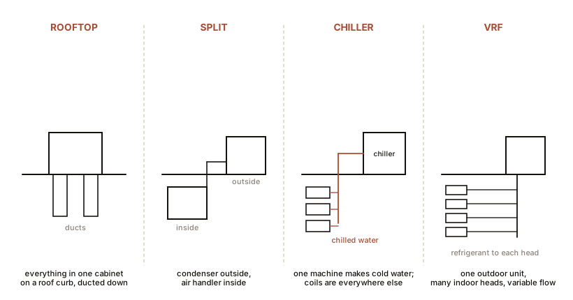
Section 8: Packaging
Four common arrangements, so a machine can be identified on sight.
Rooftop unit, RTU. Everything in one weatherproof cabinet on the roof, ducted down. Compressor, condenser, evaporator, blower, filters, economiser and controls. It is Chapter 17’s window unit at 5 to 50 tons, with all the same advantages of a single package and the same disadvantage of putting the compressor above the occupied space.
Split system, commercial. Chapter 18’s architecture at scale: air handler indoors, condensing unit outdoors, long line sets. Everything in Chapter 18 about line sizing, oil return and vertical lift applies with more force, because the runs are longer.
Air-cooled chiller. Makes chilled water rather than cold air, typically at 7 °C (44 °F), and pumps it to coils throughout a building. Refrigerant stays in the chiller; only water leaves it. Far easier to distribute cooling around a large building through pipes than through ducts.
Water-cooled chiller with a cooling tower. The condenser rejects to water instead of air, and that water rejects to atmosphere in a cooling tower by evaporation, which is Chapter 2 and Chapter 14 at industrial scale. The tower’s performance is limited by the wet-bulb temperature, not the dry-bulb, exactly as the Persians were, which is why a water-cooled plant can achieve lower condensing temperatures than any air-cooled machine and is therefore more efficient. The price is a water system, chemical treatment, and Legionella management.
Section 9: The Field Checklist
Everything in this chapter, as a sequence for someone standing in front of an unfamiliar commercial machine.
Before touching anything:
- Read the nameplate completely. Model, serial, refrigerant type and charge weight, voltage and phase, RLA, LRA, MCA, MOCP, and the metering device type if stated.
- Confirm the supply voltage matches, line to line and line to neutral, with a meter. Do not assume from the building.
- Check phase sequence if the machine has a scroll or screw compressor and any electrical work has been done.
Running:
- Clamp each leg and compare against RLA. Compare the three legs against each other: imbalance above about 2 percent indicates a supply problem, and above 5 percent will shorten the motor’s life.
- Suction and discharge pressures, converted to saturation temperatures per Chapter 7.
- Superheat and subcooling per Chapter 12, at each circuit independently on a multi-circuit machine.
- Air temperature rise across the condenser and split across the evaporator, per Chapter 9 and Chapter 12.
- Condenser entering air temperature against ambient in open shade. More than 2 to 3 °C (4 to 5 °F) means recirculation.
Then the things only commercial equipment has:
- Which stages are running, and has each one been proved? A two-compressor machine running happily on one circuit while the other has been failed for a year is extremely common, because it cools adequately on mild days.
- Crankcase heaters energised? Measure current, do not assume.
- Low ambient provision, if the machine must run in winter. Note whether it exists.
- Log run time, because Section 7 means that is your only fault history.
ON THE BENCH: Read a commercial nameplate
Parts: access to any commercial rooftop unit, chiller or condensing unit. Any commercial building, any supply house, any equipment yard. Cost: nothing. Time: 30 minutes. Hazards: do not open electrical compartments. Nameplates are on the outside for a reason. Record every field, then work out from the plate alone: - What voltage and phase does it need, and what would happen on the wrong one? - What is the LRA to RLA ratio, and what starting method would you expect? - What wire size does MCA imply, and what is the largest legal breaker? - How many refrigerant circuits, and how much charge in each? - What refrigerant, and from Chapter 8, what oil and what GWP? You should be able to answer all of that from a metal plate, and doing it once on a real machine converts this chapter from reading into skill.
Section 10: What This Chapter Bought You
Three phase gives a rotating field for free, which is why every industrial motor uses it, and why the order of three wires is not arbitrary.
MCA sizes the wire, MOCP limits the breaker, and they are deliberately different because LRA is five to eight times RLA.
A three-phase scroll run backwards destroys itself in minutes, so rotation is verified after any electrical work, always.
Capacity is staged, by multiple compressors, unloaders, digital scrolls, hot gas bypass or variable speed, because a machine with one output short-cycles.
Cold weather brings two separate problems: low ambient, which is a pressure-difference problem needing head-pressure control, and refrigerant migration, which needs a crankcase heater and a waiting period before starting.
And the safeties are auto-reset with no output contact, so faults leave no trace and the only workable monitoring is a short-cycling rule derived from logged current.
Chapter 21 takes all of it to a specific room with three machines in it.

Bench Degree
Get the degree without the diploma.
Learn the material, not how to pass the exam.