Bench Degree·REFRIGERATIONchapter

Chapter 17: The Window Unit
The simplest complete refrigeration machine ever mass produced. One chassis, one motor turning two wheels, and a wall running through the middle of it. Take one apart and you have taken all of them apart.
Everything up to here has been principle. This chapter is the first real machine, and a window air conditioner is the right one to start with for a reason that is not obvious: it is the only common machine where both halves of the loop are in the same box.
A split system hides half of itself outside. A refrigerator buries its condenser behind a panel. A rooftop unit is on a roof. A window unit puts the evaporator, the condenser, the compressor, the metering device and both fans on a single steel chassis about 500 mm (20 in) wide, with the dividing line between indoors and outdoors running straight through it.
You can see the whole cycle at once, touch every station from Chapter 10, and buy one for nothing from a kerbside in October.
Get one now if you have not already. The Bench flagged this: the supply is seasonal, and this chapter and Chapter 22 both want one you can destroy.
Section 1: The Layout
Stand in front of a window unit as installed. The front grille faces the room; the back faces the garden. Between them, inside the case, is a partition.
Indoor side of the partition:
- The evaporator coil, immediately behind the front grille, with a filter in front of it.
- The blower, usually a squirrel-cage or centrifugal wheel, drawing room air through the filter and coil and pushing it back into the room.
- The controls: thermostat, selector switch, and on modern units a small circuit board.
- The drain pan under the evaporator, catching the water of Chapter 14.
Outdoor side of the partition:
- The condenser coil, at the very back.
- The condenser fan, an axial propeller drawing outdoor air through the condenser coil and blowing it back out.
- The compressor, a black steel dome bolted to the base, usually rotary on small units and reciprocating on larger.
- The metering device, almost always a capillary tube, tucked alongside the suction line.
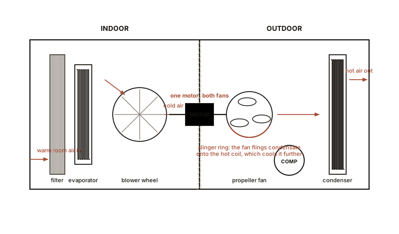
And the piece of design that makes it all work: one motor, two fans. A single shaft runs through the partition, with the blower wheel on the indoor end and the propeller on the outdoor end. One motor, one bearing set, one winding, two completely different jobs. It is a genuinely elegant economy and it is why these machines can be sold so cheaply.
Section 2: The Slinger Ring, Which Is Cleverer Than It Looks
Chapter 14 established that the evaporator condenses water out of the room air, and that on a humid day this can be several litres an hour. That water collects in the indoor drain pan. Where does it go?
On a window unit it goes into the outdoor airstream, deliberately, and gets evaporated.
The base pan is designed to let condensate flow from the indoor side to the outdoor side, where it pools in a shallow reservoir. The condenser fan’s propeller has a slinger ring on its outer rim: a raised lip that dips into that reservoir and flings water outward onto the hot condenser coil.
Two things happen, and both are useful.
The water is disposed of without a drain pipe, a pump or a hose, which is why a window unit needs no plumbing.
And the condenser gets more efficient. The water evaporating off the hot coil absorbs its full latent heat of vaporisation, about 2,450 kJ/kg (1,050 Btu/lb), directly out of the condenser. This is evaporative cooling of the condenser, which lowers condensing temperature, which by Chapter 13’s argument raises the COP of the whole machine.
So the machine takes the water it removed from the room and uses it to cool its own hot side. That is Chapter 2’s evaporative cooling and Chapter 14’s dehumidification and Chapter 13’s efficiency argument all doing one job together.
IN PLAIN ENGLISH: A window unit throws the water it wrings out of your room onto its own outdoor coil, where it evaporates and makes the machine work better. The dripping you hear is not a leak; it is the machine using its own waste product.
And it explains the commonest complaint. A window unit that drips indoors almost always has a blocked or tilted base pan: either the drain path is plugged with debris, or the unit was installed level or tilted backwards instead of very slightly downward toward the outside. The fix is nearly never refrigeration work.
Section 3: The Controls, Which Are Almost Nothing
A window unit’s control system is worth studying precisely because it is so simple that nothing is hidden.
The thermostat. On older units, a capillary bulb thermostat: a sealed tube filled with a volatile fluid, with its bulb clipped in the return airstream. As the air warms, the fluid’s pressure rises, and at a set point that pressure trips a snap-action switch. That is Chapter 7’s saturation curve used as a sensor. No electronics, no power, no calibration drift, and it works for thirty years.
The selector switch. A rotary switch selecting fan speed and whether the compressor is enabled. On the simplest units, “fan only” energises the motor and not the compressor.
The run capacitor. A single-phase motor cannot start itself, because a single alternating winding produces an oscillating field rather than a rotating one. A capacitor in series with an auxiliary winding shifts the current in that winding out of phase, and the combination produces a genuinely rotating field. That is why the machine starts at all, and it is Chapter 7 of the companion Electromagnetism volume arriving in an appliance.
A failed run capacitor is the single commonest fault on this class of machine. The compressor hums, draws heavy current, and does not start, then trips on its internal overload. It is a five dollar part.
The overload. A bimetallic disc, either external on the compressor terminals or buried inside the hermetic shell, that opens on excess current or temperature and closes again when it cools. Auto-reset, and it exposes no contact to the outside world. Remember that: Chapter 22 shows the same design decision on twenty-ton commercial equipment, where its consequences are much more annoying.
Section 4: Taking One Completely Apart
ON THE BENCH: Full teardown
Parts: a scrap window unit; screwdrivers; a socket set; a tubing cutter; gloves; eye protection; a camera; a permanent marker; a tray for screws. Cost: nothing. Time: two to three hours, and worth every minute.
Hazards, and read all of them. - Unplug it and leave it unplugged. Then discharge the run capacitor by shorting its terminals through a 20 kΩ resistor or an insulated screwdriver. A capacitor holds a dangerous charge for a long time after power is removed and has injured people who assumed otherwise. - The system is charged. Do not cut into refrigerant lines with a saw. If you want the lines open, use a tubing cutter and let it vent slowly, and understand that in most jurisdictions deliberate venting is illegal. The correct route is a recovery machine, and for a scrap unit the lawful and easy option is to leave the sealed system intact and study it from outside. - Coil fins cut like razors. Gloves, and mean it. - The compressor is heavy and the chassis has sharp edges.
Method, and photograph every stage. 1. Slide the chassis out of the outer case. Everything is now visible. 2. Identify all four components from Chapter 9 and mark each with the marker. Do this before removing anything. 3. Trace the refrigerant circuit with a finger, start to finish, and write the station numbers from Chapter 10 on the tubing itself. 4. Find the capillary tube. Note that it runs soldered alongside the suction line for part of its length. Ask yourself why before reading Section 5. 5. Remove the front grille and filter. Look at the evaporator fins and count them per inch. 6. Find the drain path from the indoor pan to the outdoor reservoir, and find the slinger ring on the fan. 7. Remove the fan assembly and confirm the single shaft crossing the partition. 8. Open the control box. Identify thermostat, selector switch, capacitor and overload. Draw the wiring as a schematic.
What you should end up with: a labelled photographic record and a hand-drawn schematic of a complete refrigeration machine, made by you, from an object that cost nothing. That document is worth more than this chapter.
Section 5: The Detail Worth Noticing
Step 4 of the teardown asked why the capillary tube is soldered against the suction line. It is the neatest piece of design in the machine.
The capillary carries warm high-pressure liquid toward the evaporator. The suction line carries cold low-pressure vapour away from it. Braze them together and heat flows from the liquid into the vapour.
Two benefits at once.
The liquid gets subcooled before it reaches the restriction. Chapter 10 Section 5 showed why that matters: more subcooling means less flash gas, which means more of the refrigerant is available to do useful cooling. Free capacity.
And the vapour gets superheated before it reaches the compressor. Chapter 9’s one rule: liquid destroys compressors. This arrangement guarantees dry vapour with no extra parts.
The device has a name, a suction line heat exchanger, and on a window unit it costs nothing: it is two pipes and some solder. It appears again on commercial equipment as a proper brazed-plate component, and there it is a line item.
SLOW DOWN. Check Your Understanding: Heat flows from the liquid line into the suction line. Has any heat been added to or removed from the system as a whole? Think before reading on.
No. The heat has merely been moved from one part of the loop to another. Nothing entered from outside and nothing left. What changed is where in the cycle the refrigerant carries its heat, and that redistribution improves both ends. This is a genuinely free improvement, which is rare enough to be worth pausing on: no energy input, no extra component, only better arrangement.
Section 6: Why the Whole Machine Is Also Its Own Worst Problem
Two structural weaknesses follow directly from the single-chassis design, and both are worth understanding because the split system of Chapter 18 exists to fix them.
Noise. The compressor is bolted to the same chassis as the indoor blower, half a metre from a person’s head, with only a thin partition and a foam gasket between. There is no way to make that quiet. A split system moves the compressor outdoors and the difference is not marginal.
Air leakage and heat conduction through the partition. The partition is thin steel with holes in it for a motor shaft and refrigerant lines. Heat conducts straight through it from the hot side to the cold side, and air leaks around the sleeve. Both losses are small in absolute terms and are a permanent tax on efficiency, and they are the main reason a window unit’s SEER is far below a split system’s.
And one more, which is about installation rather than design: the unit is a hole in a wall. Even perfectly fitted, a window unit is a worse thermal boundary than the window it replaced.
Which is why the next chapter cuts the machine in two.
Section 7: The Variants
Three relatives worth recognising, because they are the same machine rearranged.
The through-the-wall unit (PTAC, packaged terminal air conditioner) is the machine every hotel room has under the window. Identical architecture, mounted in a wall sleeve rather than a window, and almost always fitted with a reversing valve so it is also a heat pump. Chapter 19 explained that valve. A PTAC is the cheapest way to see one.
The portable unit on wheels, with a hose to a window. Architecturally the same, but with a serious flaw worth naming because these are sold heavily. A single-hose portable unit exhausts room air out of the window, which means the room is at slightly negative pressure and pulls an equal volume of hot outdoor air in through every gap in the building. It is cooling air and simultaneously importing heat. A dual-hose unit takes its condenser air from outside and returns it outside, which fixes the problem entirely. The price difference is small and the performance difference is large.
The dehumidifier is a window unit with both coils indoors and no partition at all. Air passes over the evaporator, gets cooled below the dew point, drops its water, then passes over the condenser and is reheated. Net effect: the room gets drier and slightly warmer, because the compressor’s electrical input has nowhere to go but into the room. Which answers a question people ask constantly: a dehumidifier heats the room it dries, and that is not a defect, it is Chapter 10’s energy accounting with both coils on the same side of the wall.
Section 8: What This Chapter Bought You
One chassis, both halves of the loop, a partition through the middle, and one motor turning two fans.
Every station of Chapter 10 is touchable on this machine, which is why it is the right one to dismantle first.
The slinger ring throws condensate onto the condenser, disposing of the water and improving efficiency in one move.
The controls are almost nothing: a saturation-curve thermostat, a switch, a run capacitor and an auto-reset overload with no external contact. That last detail scales all the way up to Chapter 22.
The capillary tube is brazed to the suction line to subcool the liquid and superheat the vapour at once, for free.
And the design’s weaknesses define the next chapter. Noise and a leaky conductive partition are exactly what a split system exists to solve.
Chapter 18 cuts the machine in half and runs copper between the pieces.

Bench Degree
Get the degree without the diploma.
Learn the material, not how to pass the exam.