Bench Degree·WIND POWERchapter
Chapter 1: Two Rotors and a Box Fan
Two rotors the same size, in the same wind. One of them makes three times the power. Then a ribbon on a blade tip shows you something that sounds impossible.
You are going to build two rotors this afternoon, and the comparison between them is four thousand years of history delivered in about twenty minutes.
Both are the same diameter, roughly 300 mm (12 in). Both drive the same generator, which is a small hobby motor run backwards. The only differences are the shape of what catches the wind and the direction that shape has to face, and the second one turns out to matter as much as the first.
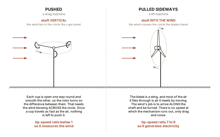
Rotor A is cups. Four halves of a ping-pong ball, or four paper cups, glued to cross-arms so that each one presents its open side one way round and its smooth back the other. This is an anemometer, and it is also, in essence, every windmill built before about 1750. The wind pushes on the cups. That is the whole mechanism.
And that mechanism only works if the wind blows across the circle the cups travel in. A cup that is open to the wind catches it; the cup on the far side of the hub has its smooth back turned to the same wind and catches less. The rotor turns on the difference between those two, so the wind has to be able to see one cup’s mouth and the other cup’s back at the same time. Point the shaft straight at the fan instead and every cup presents the same aspect to the air, the difference vanishes, and the thing sits there. So Rotor A runs with its shaft vertical, cups sweeping a horizontal circle, which is exactly how every cup anemometer on every weather mast is mounted.
Rotor B is wings. Four blades cut from thin plywood or stiff card, each one twisted so its flat face is turned about 20 degrees away from the plane of rotation, with the leading edge rounded and the trailing edge left sharp. These are not cups. They are small aircraft wings.
A wing wants the opposite. It needs air flowing over it from leading edge to trailing edge, and on a spinning rotor most of that flow comes from the blade’s own motion through the air. The wind’s job is to arrive along the shaft and be turned. So Rotor B runs with its shaft pointing straight at the fan, blades facing the wind, which is how every horizontal-axis turbine ever built is mounted.
Two machines, two orientations, and the orientations are not interchangeable. That is not a detail of the build. It is the first thing this book has to teach you, because it is the physical difference between being pushed and flying.
Stand a box fan on its edge so it blows horizontally, and hold each rotor in the stream in turn, at the same distance each time, each in the orientation it needs: Rotor A shaft vertical, Rotor B shaft aimed at the fan. Do not lay the fan flat on the floor facing upward: a box fan draws through its whole rear face, and putting that face against the floor chokes the intake and you will be measuring the floor rather than the rotor. If you have nothing to stand it against, set it on the seat of a chair with the back of the fan overhanging the edge so air can reach it.
Measure the voltage across the motor’s terminals with a multimeter.
Rotor A, the cups, will give you something. Rotor B, the wings, will give you three to five times as much.
Same wind. Same diameter. Same generator. The difference is entirely that one rotor is being pushed and the other one is flying.
Worth knowing before you compare the two numbers: the two rotors are the same diameter, but they are not intercepting the same area of wind. Rotor B sweeps a disc and works on all of it. Rotor A only ever presents the frontal profile of whichever cups happen to be on the advancing side, which is a fraction of its circle. A drag machine’s capture area is its silhouette, not its sweep, and that alone accounts for part of the gap. Chapter 5 does this properly, because getting the area wrong is how people accidentally claim to have beaten the Betz limit.
ON THE BENCH: Cups against wings
Parts: a box fan; a small DC hobby motor with a shaft; wine corks for hubs; four paper cups or ping-pong balls; a scrap of 3 mm (1/8 in) plywood or stiff card; skewers for arms; hot glue; multimeter. Everything else: every part this book asks for is listed once, at the back, in Appendix A: The Bench. Nothing is specified by brand, so it can be ordered from anyone. You do not need any of it yet. Cost: about $15 if you own the fan. Time: 45 minutes to build both, 5 minutes to measure. Hazards: keep fingers out of the fan. Balance the rotors roughly or they will shake themselves apart. Small motors get warm. The mistake to expect: holding the cup rotor face-on to the fan the way you hold the winged one. It will barely move, and it is not a bad build. Turn its shaft vertical and it will run. What you should see: the winged rotor producing three to five times the open-circuit voltage of the cup rotor, and spinning visibly faster. Record: voltage from each rotor at the same fan setting and the same distance. Those two numbers are the whole of Chapter 4.
Section 1: The Ribbon, Which Is the Part That Breaks People
Cut a strip of light ribbon or a thread about 100 mm (4 in) long and tape it to the tip of one blade of the winged rotor. Run the rotor up in the fan stream and watch the ribbon.
The blade tip is moving several times faster than the air coming out of the fan.
Time it if you doubt your eyes. Count revolutions in ten seconds, multiply by the circumference, and you have tip speed. Then measure the fan’s air speed with a cheap vane anemometer, or by timing a scrap of tissue drifting across a known distance. On a decent winged rotor the tip speed will be five, six, seven times the wind speed.
A machine driven by a breeze is outrunning the breeze that drives it. By a factor of six.
This feels like it must be wrong. If the wind is what pushes the blade, how can the blade outpace the wind? A sailing boat cannot outrun the wind going downwind, and the cup rotor certainly cannot: its cups can never travel faster than the air pushing them, because at that point the air would be catching up rather than pushing.
The winged rotor is not being pushed. It is generating lift, which acts at right angles to the airflow rather than along it, exactly as an aircraft wing does. And because the force is sideways, it can drive the blade around the circle at a speed that has nothing much to do with how fast the air is moving forwards. Chapter 4 does the vectors properly, and once you have seen them the impossibility evaporates.
IN PLAIN ENGLISH: A cup rotor is pushed by the wind and can never move faster than it. A winged rotor flies, and its tips can travel many times the wind speed. This one difference is why Persian windmills ground grain for a thousand years and never made a kilowatt, and why every modern turbine has three slender blades that look nothing at all like a sail.
Section 2: The Third Demonstration, and the Number That Runs the Industry
Leave everything set up. Put the winged rotor back in the stream and measure the output with the fan on low. Write it down. Now switch the fan to high and measure again.
The air speed has roughly doubled, or a little less. Measure it if you can, and note the ratio.
The power has gone up by a factor of six to eight.
Not two. Not three. Roughly eight, if the speed exactly doubled.
Do the multiplication if you measured voltage into a fixed resistance: power goes as voltage squared, so a voltage that rose by 2.8 times means a power that rose by nearly 8 times.
This is the single most important number in wind energy, and it is the reason the whole industry looks the way it does.
P = ½ ρ A v³Power is one half, times the air’s density, times the swept area, times the wind speed cubed. Chapter 1’s remaining sections build that equation from scratch. But you have just measured the exponent with a fan switch, which is a better way to learn it than being told.
SLOW DOWN. Check Your Understanding: Site A has an average wind speed of 5 m/s (11 mph). Site B averages 6 m/s (13 mph), only twenty percent more. How much more energy will an identical turbine produce at Site B? Work it out before reading on.
(6/5)³ = 1.728, so about 73 percent more, from a wind that is only twenty percent stronger. This is why wind developers spend years and considerable money measuring a site before committing to it, and why a cheap turbine at a good site beats an excellent turbine at a mediocre one every single time.
Section 3: Where the Equation Comes From
Now the derivation, with the reader already holding the result.
Air has mass. This is the part that is easy to forget because air is invisible and feels like nothing. At sea level and ordinary temperature, air has a density of about 1.225 kilograms per cubic metre, which is about 0.0765 pounds per cubic foot. A modest bedroom holds something like 50 kg (110 lb) of it, roughly the mass of a person.
Moving mass has kinetic energy, and the formula for that is one every engineer already knows:
KE = ½ m v²Now consider a hoop of area A standing in the wind, with air passing through it at speed v. In one second, how much air goes through?
A column of air, of cross-section A and length v, because anything
within v metres upstream will have arrived by the end of that second.
Its volume is A × v, and so its mass is
m = ρ A vSubstituting that mass into the kinetic energy expression, and remembering that energy per second is power:
P = ½ (ρ A v) v² = ½ ρ A v³And there is the cube. It comes from the fact that faster wind carries not only more energy per kilogram, but more kilograms per second. Two factors of v from the kinetic energy, one more from the increased mass flow. Three altogether.
IN PLAIN ENGLISH: Double the wind and each kilogram of air carries four times the energy, and four times as many kilograms arrive each second. Four times four is not right, because one of those factors was already counted; the honest arithmetic is two squared for energy and two for flow, giving eight.
What the numbers actually look like
For a 1 square metre hoop (about 10.8 square feet) at sea level:
| Wind speed | Power in the wind | |
|---|---|---|
| 5 m/s | 11 mph | 77 W |
| 10 m/s | 22 mph | 613 W |
| 15 m/s | 34 mph | 2,067 W (2.1 kW) |
| 20 m/s | 45 mph | 4,900 W (4.9 kW) |
| 25 m/s | 56 mph | 9,570 W (9.6 kW) |
Look at the spread. From a pleasant breeze to a strong gale, one square metre goes from powering a light bulb to powering a house. That table is why turbines are shut down in storms rather than left to make a fortune, a question Chapter 14 answers properly.
And notice the other term. Power goes as A, the
swept area, which for a circular rotor is πr². Double the
rotor diameter and you quadruple the area and therefore the power. That
is the entire reason turbines have grown from 15 metre rotors in 1980 to
more than 220 metres (720 ft) today, and why they will keep growing
until materials stop them.
Section 4: What You Cannot Have
One more thing before the chapter closes, stated now and proved in Chapter 5, because it is the most elegant result in the subject and it is worth looking forward to.
You might think a perfect turbine would extract all of the power in that table. It cannot, and the reason has nothing to do with engineering quality.
To take all the kinetic energy out of the air, you would have to bring the air to a complete standstill behind the rotor. But stopped air cannot get out of the way of the air arriving behind it. The flow would block, and nothing would pass through the rotor at all, and you would extract nothing.
So taking nothing gives you nothing, and taking everything gives you nothing. Somewhere in between there is a maximum, and in 1919 Albert Betz worked out exactly where it is: you can never extract more than 16/27 of the wind’s power, which is 59.3 percent. Not with better blades, not with better materials, not ever.
Betz is the man on the cover of this book, and Chapter 5 derives his limit with no calculus at all.
Section 5: Where This Book Is Going
By the last page you will be able to stand under any wind turbine and do the following.
- Say roughly what it produces at 7 m/s (15 mph) and at 13 m/s (30 mph), and explain why those figures differ by a factor of six rather than two.
- Explain why it has three blades and not two or twenty, and why a farm water pump correctly has twenty.
- Say why the tower is as tall as it is, in terms of what the wind does with height.
- Explain why it stops in a storm instead of making a fortune, and what physically stops it.
- Read a power curve and identify cut-in, rated and cut-out, and explain why the curve goes flat.
- State what fraction of the wind’s energy it is physically permitted to take, and why that fraction is what it is.
- Work out whether a small turbine on your own property would pay, and be willing to arrive at the answer no, which for most rooftops it is.
Everything is built in order. Nothing arrives that has not been assembled from something earlier. If a chapter loses you, the fault is upstream, and the fix is to go back one section rather than push on.
Keep both rotors. Rotor A comes back in Chapter 2, where it turns out to be a perfectly good machine for a job that is not electricity.

Bench Degree
Get the degree without the diploma.
Learn the material, not how to pass the exam.