Bench Degree·WIND POWERchapter
Chapter 2: Four Thousand Years of Grinding and Pumping
Rotor A, the cup rotor you built in Chapter 1 and were disappointed by, ran a civilisation’s flour mills for a thousand years. It was the right machine. This chapter explains for what.
Start with an honest note about the title.
Four thousand years is generous. You will read that Hammurabi of Babylon planned to irrigate the plain of Mesopotamia with wind machines around 1700 BC, and that claim is repeated in a great many books about wind energy, and there is no documentary evidence for it. It appears to have entered the literature by repetition rather than by discovery.
What is documented is this. Hero of Alexandria describes a wind-driven organ in the first century AD, which makes it the earliest surviving description of a machine driven by air rather than by water, animals or people. Persian geographers describe working grain mills in Sistan, on what is now the Iran-Afghanistan border, by the ninth century AD. Chinese vertical-axis sail mills, used to lift brine into salt evaporation pans, are documented from around the thirteenth century. And in England and Normandy the horizontal-axis post mill appears in the written record in the 1180s, with a mill at Weedley in Yorkshire recorded in 1185.
So the honest span is about twelve hundred years of certainty and perhaps two thousand of plausibility. A number that gets repeated is not the same as a number that got measured, and this book will point that out whenever it applies, including when it applies to the wind industry’s own figures.
Section 1: The Persian Mill, Which Was a Drag Machine and Knew It
At Nashtifan in north-eastern Iran there are windmills that have been maintained more or less continuously for centuries and that still turn. They are the clearest surviving picture of the oldest well-attested design.
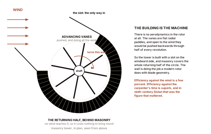
The rotor is vertical. A shaft stands upright in a masonry tower, and radiating from it are flat vanes of woven reed or timber, so the whole assembly looks like a paddle wheel stood on its end. There is no airfoil, no twist, no attempt at anything resembling a wing. The wind pushes the vanes, and the vanes go round. This is your Rotor A with better carpentry.
Which raises the obvious problem. A paddle wheel presents a vane to the wind on the way past and then has to drag that same vane back into the wind on the return half of the circle. The returning vane is pushed backwards exactly as hard as the advancing vane is pushed forwards, and the machine sits still.
The Persian solution is not aerodynamic at all. It is a wall. The tower is built with a slot on the windward side, so the wind can only reach the rotor over one half of its circle. The returning vanes are sheltered behind masonry. The building is not a housing for the machine, the building is part of the machine, and it is doing the job that a modern rotor does with blade geometry.
That works. It also puts a hard ceiling on the result, and Chapter 7 will put a number on it.
IN PLAIN ENGLISH: A machine that is pushed has to get its pusher out of the way again on the way back round. You can solve that with a shape, which is what a wing does, or with a wall, which is what the Persians did. The wall is simpler, needs no theory at all, and costs you most of the wind.
Section 2: Why They Built It That Way Anyway
It is tempting to read the Persian mill as ignorance. It was not. It was a correct answer to a differently shaped question.
A grain mill has no use for speed and a great deal of use for torque. A millstone is heavy, it starts from rest under the full weight of the stone, and it wants to be turned steadily at some tens of revolutions per minute against a grinding load that does not go away. What it does not want is a fast, light shaft that stalls the moment grain is fed in.
A drag rotor gives you exactly that. It produces its maximum torque at zero speed, which means it starts under load without help. It is indifferent to which way the wind is blowing, which matters enormously when your alternative is a mechanism that turns a whole building. It can be built by a village carpenter out of reed, mud brick and timber, with no metal bearing and no machined part anywhere in it.
And the fuel was free and the alternative was a donkey. Efficiency measured against the wind is the wrong figure of merit when the wind costs nothing and the capital is a wall you were going to build anyway. Efficiency measured against the carpenter’s time is the figure that mattered, and on that measure the Sistan mill is superb.
Keep this in mind for Chapter 15, where the same argument reappears in modern dress and is usually wrong. The question is never “is this efficient”, it is “is this the cheapest way to get the work done”. In ninth-century Sistan those had different answers. In a twenty-first-century suburb they do not.
Section 3: Europe Turns the Shaft Sideways
Somewhere before 1180, in northern Europe, somebody put the shaft horizontal. It is not clear who and it is not clear whether the idea travelled from Persia or was invented independently, and the mills that would settle the question are gone.
The consequence is not subtle. A horizontal shaft lets every blade work through the whole revolution, because the blades sweep across the wind rather than into and out of it. No wall is required. Nothing has to be sheltered. The rotor faces the wind and the entire disc is live.
The cost is that the rotor now has to be pointed. And the first solution to that is one of the great pieces of blunt medieval engineering: you turn the entire building.
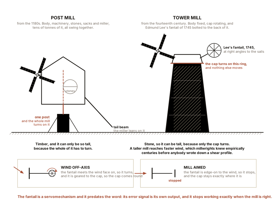
A post mill is a timber box containing the machinery, the millstones, the sacks and the miller, mounted on a single massive vertical post and turned bodily into the wind with a long tail beam that the miller leans on. The whole mill, tens of tonnes of it, pivots.
The tower mill and its timber cousin the smock mill improved on that around the fourteenth century by fixing the body and rotating only the cap. Since the body no longer has to swing, it can be built of stone and it can be built tall, and a taller mill reaches faster wind, which is Chapter 9’s subject and was understood empirically by millwrights centuries before anybody wrote down a shear profile.
The sails themselves were latticed timber frames spread with cloth, and the miller furled and unfurled the canvas to suit the wind. That is pitch control, operated by hand, and Chapter 14 is about the automation of exactly this task. In 1745 Edmund Lee patented the fantail, a small rotor set at right angles to the main sails that automatically yaws the cap into the wind. That is a servomechanism, and it predates the word.
ON THE BENCH: Drag against lift, measured properly this time
Chapter 1 compared cups with wings on voltage alone. This is the same comparison done so it yields two numbers, because a machine has two things to sell and they are not the same thing.
Parts: the winged rotor from Chapter 1; a Savonius rotor of the same swept area, made by cutting a 2 litres (0.5 gallons) drinks bottle or a length of 110 mm (4.3 in) drain pipe lengthways and offsetting the two halves on a shaft; thread; a paper cup; coins or washers; a box fan; a multimeter. Cost: under $5 on top of what you already built. Time: an hour. Hazards: cut plastic edges are sharp. Keep hands out of the fan.
Method, part one, the power. Run each rotor in the same fan stream at the same distance and record the open-circuit voltage, exactly as in Chapter 1. Then load each one with the same resistor, say 100 ohms, and record the voltage again. Power into a known resistance is voltage squared divided by resistance, so you now have real power rather than a proxy.
Method, part two, the starting torque. This is the measurement nobody makes and it is the one that explains history. Wind a thread around each rotor’s shaft, hang the paper cup from it over the edge of the bench, and add coins one at a time with the fan running and the rotor held still. Release. Find the largest load that the rotor will still lift from a standstill. Record the mass, in grams, and the shaft radius.
What you should see: the winged rotor wins on power, by a factor of three or more, exactly as before. The Savonius wins on starting torque, and it is not close. The drag rotor will lift a load from rest that leaves the winged rotor sitting there doing nothing.
If it does not work: if the winged rotor will not start at all under any load, that is the correct result and not a failure. It is also the entire reason a farm water pump does not look like a wind turbine, which is Section 5.
Better, if you have one: a small torque-arm scale, or a cheap luggage scale on a string, gives a continuous reading rather than a threshold, and lets you plot torque against speed.
Section 4: Draining a Country
The largest thing wind has ever done to a landscape was done before electricity existed.
About a quarter of the Netherlands lies below sea level, and much of that is below sea level because it was pumped dry and then compacted. The instrument was the drainage mill: a tower or smock mill whose shaft, instead of turning a millstone, turned a scoop wheel or later an Archimedes screw that lifted water from a low polder into a higher ring canal.
The critical number is the lift. A scoop wheel raises water by roughly 1.5 m (5 ft) in one stage, and no more, because a bigger wheel needs a longer paddle and the mill cannot supply the torque. So to lift water 4.5 m (15 ft) you need three mills in series, each one delivering into the next one’s intake. The Dutch called such a chain a molengang, a mill gang, and the surviving group at Kinderdijk, built in 1738 and 1740, is nineteen mills doing exactly this.
The Beemster polder, drained between 1607 and 1612 with about forty mills, turned a lake into forty square kilometres (fifteen square miles) of farmland. At the peak of the technology the Netherlands had something on the order of nine thousand working windmills. Around a thousand survive.
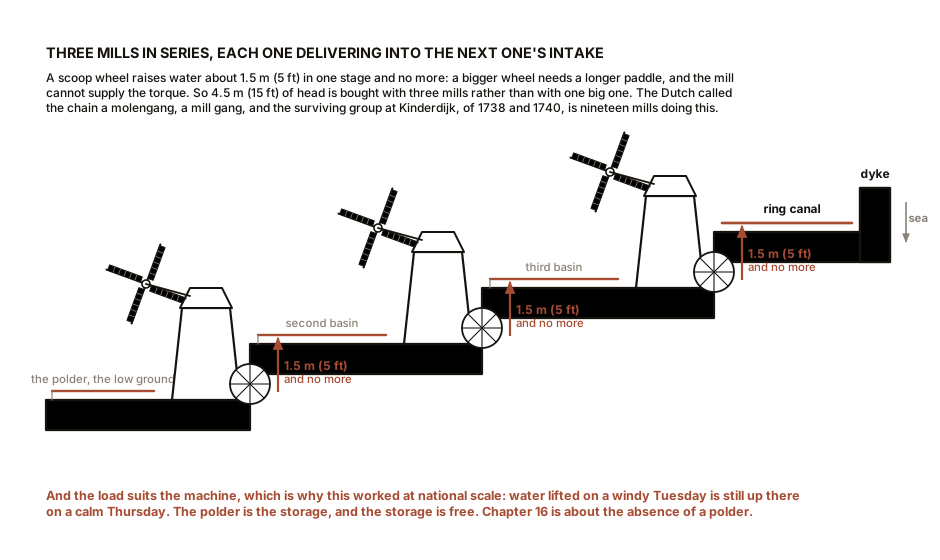
This is the first industrial application of wind at national scale, and it succeeded because the load suited the machine. Pumping is the ideal wind load: it does not care when it happens. Water lifted on a windy Tuesday is still up there on a calm Thursday. The polder is the storage, and the storage is free. Chapter 16 spends a lot of effort on why electricity is harder, and the whole of that difficulty comes down to the absence of a polder.
ON THE BENCH: Why they needed nineteen mills
Parts: a shallow tray or baking dish; a second tray propped 60 mm (2.4 in) higher; a disc of stiff card about 150 mm (6 in) across with six paddles glued radially to its rim; a skewer axle; your hobby motor or just your fingers; a jug of water; a stopwatch; a kitchen scale. Cost: nothing. Time: 30 minutes. Hazards: water and electricity do not mix. Keep the motor out of the splash zone, or turn this rotor by hand.
Method: set the scoop wheel so its lower paddles dip into the full tray and its rising paddles carry water over the lip into the higher tray. Turn it steadily for 60 seconds and weigh what you moved. Now prop the upper tray higher, to 120 mm (4.7 in), and repeat at the same speed.
What you should see: at the greater lift the wheel moves far less water per turn, and the effort in your fingers rises sharply, because a paddle now has to carry its load through a longer arc before it can tip. Push the lift high enough and the wheel simply carries the water round and drops it back where it came from. You have just found the physical reason a scoop wheel is limited to about 1.5 m (5 ft) of head, and therefore the reason the Dutch stacked mills instead of building bigger ones.
Section 5: The American Farm Windmill, Which Is Not a Turbine
In 1854, in Connecticut, a mechanic named Daniel Halladay patented a windmill for the American plains. It has twenty or more slender sheet-metal blades on a small wheel, a tail vane, and a crank driving a reciprocating pump rod down a well casing. Six million or so of them were installed in the United States between the 1850s and the 1970s, and they made the settlement of the dry interior possible, because a homestead without water is not a homestead.
It is not a wind turbine and it should not be judged as one. Look at what the load demands.
A reciprocating well pump has to break out from rest against the full weight of the water column standing in the riser. That is a large torque at zero speed and a modest torque thereafter. And the machine has to do it unattended, in whatever wind arrives, without anybody there to help it start.
So the design answers are forced. Many blades, filling most of the disc, because torque at low speed scales with how much blade area you have. A low tip-speed ratio, near one, because you cannot spin a piston pump fast anyway. A self-regulating mechanism, which was Halladay’s real invention: the sails hinge and swing edge-on as the wind rises, so the mill sheds power instead of tearing itself apart, with nobody watching.
Then came the refinement that matters most to this book. In the 1880s Thomas O. Perry, working at the U.S. Wind Engine and Pump Company, ran an experimental programme on wind wheels: several thousand individual tests of blade shape, curvature and setting angle, on a whirling arm and in a fan-driven rig. He did on a bench precisely what this series asks you to do. The curved steel blade that came out of it was dramatically better than the flat wooden paddles it replaced, and in 1888 it became the Aermotor, which is still manufactured.
Perry’s result is worth stating carefully, because it is often quoted as a percentage without saying a percentage of what. He compared curved sheet-steel sails against the flat wooden sails then standard, at the same wheel diameter, and found the curved sails delivered substantially more power, on the order of a third to a half again. The mechanism is that a curved plate develops some lift, and lift is worth more than drag. That is Chapter 4, discovered empirically by a man with a fan and a lot of patience, twenty years before anyone wrote down a theory of the airfoil.
SLOW DOWN. Check Your Understanding: A farm windmill has about twenty blades and turns at perhaps 40 rpm in a moderate breeze. A power turbine of the same diameter has three blades and turns much faster. Both are pointed into the same wind. Which one takes more energy out of the wind, and which one produces more torque at the moment it starts? Answer both before reading on.
The three-blade machine takes far more energy. The twenty-blade machine produces far more starting torque. Those are different questions, and this is the point where most people’s intuition fails, because it feels as though more blades must catch more wind.
They do not, and here is why. Power is torque multiplied by rotational speed. The farm windmill has perhaps four times the torque coefficient and one seventh of the speed, so it loses on the product. More blades also interfere with each other: each blade runs in the disturbed air shed by the blade ahead of it, and past a certain solidity you are adding drag without adding useful lift. Chapter 6 makes that quantitative.
But notice what the farm windmill bought with the trade. It starts under load, unattended, in a light wind, against a standing water column, and it did that on hundreds of thousands of farms for a century with a grease gun as its only maintenance. The turbine cannot do any of that. Neither machine is better. They are answers to different questions, and the physics is the same physics.
Section 6: What the Long Road Actually Teaches
Four things, and they all get used later.
Drag machines start well and finish badly. They give torque from a standstill and they never take much of the wind. If your load needs torque and does not need much power, that is a feature.
Lift machines finish well and start badly. They take several times more of the wind and often cannot get themselves moving under load. If your load can be arranged to arrive gently, which an electrical generator’s load can, that is a fair trade.
Somebody has to point the rotor, and the history of that problem runs from a miller leaning on a tail beam, through Lee’s fantail of 1745, to the yaw motors and wind vane of Chapter 12. It is the same problem each time.
And the load determines the machine, not the other way round. A millstone wanted torque. A polder wanted a pump whose output could be stored in the landscape. A well wanted starting torque and self-regulation. Every one of those got a different rotor, correctly.
What none of them wanted was electricity, because there was none. When there finally was, in 1888, the first two people to try it built machines that look nothing like each other and only one of them was on the right track. That is Chapter 3.

Bench Degree
Get the degree without the diploma.
Learn the material, not how to pass the exam.