Bench Degree·WIND POWERchapter
Chapter 18: What You Now Know
Chapter 1 made seven promises about what you would be able to do standing under a turbine. Here they are, one at a time, with the answers filled in and one of them corrected, because the promise as written was slightly wrong and you can now see why.
Chapter 1 ended with a list. It said that by the last page you would be able to stand under any wind turbine and do seven specific things. A book that makes a list like that owes the reader a line-by-line audit, so here it is, in the order it was promised, with the honest verdict on each.
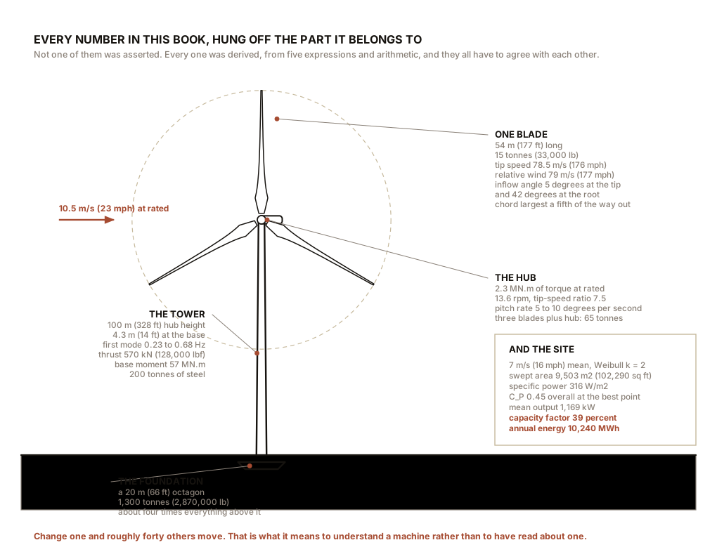
Throughout, the reference machine is the one the book has carried since Chapter 11: 3 MW rated, rotor 110 m (361 ft), swept area 9,503 square metres (102,290 square feet), hub height 100 m (328 ft), rated wind speed 10.5 m/s (23 mph), rotor speed 13.6 rpm at rated, tip speed 78.5 m/s (176 mph), at a site with an annual mean wind speed of 7 m/s (16 mph) and a Weibull shape factor of 2.
Section 1: The Seven Promises, Audited
Promise one. Say roughly what it produces at 7 m/s (16 mph) and at 13 m/s (29 mph), and explain why those figures differ by a factor of six rather than two.
At 7 m/s (16 mph) it produces about 900 kW. At 13 m/s (29 mph) it produces 3,000 kW, which is its rated maximum.
at 7 m/s:   0.45 × ½ × 1.225 × 9,503 × 7³   =  898 kW
at 13 m/s:  rated, so 3,000 kW
And here is where the promise needs correcting, using exactly
the tools the book supplied. The wind’s power at those
two speeds differs by a factor of (13/7)³, which is
6.4, and Chapter 1 was entirely right about that. But
the machine’s output differs by only 3.3,
because 13 m/s (29 mph) is above the rated speed of 10.5 m/s (23 mph)
and Chapter 13 showed the curve goes deliberately flat there.
So the corrected answer, which is a better answer, has two halves. The cube law is real and the factor of six is real, and it governs everything below rated. Above rated the machine declines the increase on purpose, for the reasons in Chapter 13 Section 3, and the shape of a power curve is a decision rather than a limitation.
A reader who gives the factor of six is right about the wind. A reader who gives 900 kW and 3,000 kW and explains why the ratio is not six is right about the machine, and that second answer is the one this book was written to produce.
Promise two. Explain why it has three blades and not two or twenty, and why a farm water pump correctly has twenty.
Not two, because Chapter 6 showed that three or more equally spaced blades give a rotor whose moment of inertia about the yaw axis is exactly the same at every azimuth, while a two-blade rotor’s varies twice per revolution and its aerodynamic loads add into a rocking couple. A two-blade machine therefore needs a teetering hub, and the industry has repeatedly judged a third blade cheaper than a large safety-critical hinge in the least accessible part of the machine.
Not four or five, because beyond three the extra capture is under one percent while the cost of blades and hub rises by a third.
Not twenty, because twenty blades force a low tip-speed ratio, and Chapter 6 showed that a slow rotor loses heavily to wake swirl and needs an enormously expensive high-torque drivetrain. It also puts every blade in the disturbed wake of the one ahead of it, which is what Chapter 3’s Brush machine discovered the hard way with 144 of them.
And the water pump correctly has twenty because it needs torque at zero speed against a standing column of water, unattended, and torque at zero speed is what high solidity buys. Its starting torque coefficient is around 0.5 against the power turbine’s 0.02, a factor of twenty-five. The same physics, two loads, two right answers.
Promise three. Say why the tower is as tall as it is, in terms of what the wind does with height.
Because Chapter 9’s boundary layer means wind speed rises with height
as h^α, so energy rises as h^(3α), while tower
cost rises as roughly h². The benefit exponent is
3α and the cost exponent is 2, and since α is never above about 0.4,
cost always wins eventually. Where it wins is set by the
terrain: offshore, α of 0.10 means climbing barely pays and hub height
is set by wave clearance instead; over forest, α of 0.30 means 160 m
(525 ft) hybrid towers are rational.
And past about 120 m (394 ft) the answer stops being physics. Tubular steel tower bases are limited to about 4.3 m (14 ft) diameter because that is what fits under a bridge, and beyond that height a tube of legal width is too flexible. The tallest towers in the world are concrete or site-assembled because of road geometry.
Promise four. Explain why it stops in a storm instead of making a fortune, and what physically stops it.
Why: three reasons, in order. Loads, because rotor thrust goes as the square of wind speed and at 25 m/s (56 mph) it is thirteen times what it is at 7 m/s (16 mph), outside the structural envelope the tower and foundation were built to. Fatigue, because Chapter 9’s tenth-power rule means an hour of generating in a gale consumes more blade life than a month of ordinary running. And energy, because the wind blows above cut-out for a matter of hours a year and those hours carry well under one percent of the annual energy. It is declining a rounding error at enormous risk.
What physically stops it: the blades. The pitch system feathers all three to about 90 degrees at 5 to 10 degrees per second, so the chord lies along the wind and the driving torque collapses. That is the primary brake and it is aerodynamic. The generator absorbs torque as a secondary brake. The mechanical disc brake on the high-speed shaft is a parking brake, sized to hold a stopped rotor rather than to arrest a running one, and Chapter 12 explained that using it the other way would destroy it. Older stall-regulated machines with no pitch system use centrifugally deployed tip brakes instead.
Promise five. Read a power curve and identify cut-in, rated and cut-out, and explain why the curve goes flat.
Cut-in, 3 m/s (7 mph), set not by what the rotor can turn but by where output exceeds the machine’s own parasitic consumption of 10 to 30 kW. Rated, 10.5 m/s (23 mph), the lowest speed at which nameplate is reached. Cut-out, 25 m/s (56 mph), with a restart hysteresis around 20 m/s (45 mph) so the machine does not chatter.
Flat because everything downstream of the blades is sized by power rather than by wind. At 25 m/s (56 mph) there is 91 MW in the wind and 41 MW would be theoretically takeable, so catching it would require a drivetrain fourteen times larger, used for hours a year. The flat top is the cheapest decision in the machine.
Promise six. State what fraction of the wind’s energy it is physically permitted to take, and why that fraction is what it is.
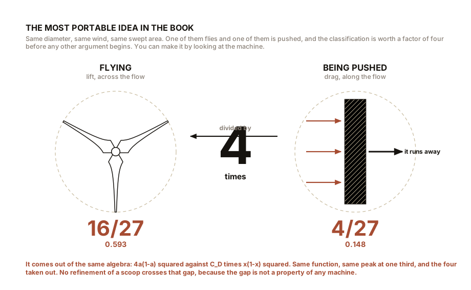
16/27, which is 59.3 percent, and the reason is that
the wind at the disc must be the arithmetic mean of the wind far
upstream and far downstream, which falls out of setting the momentum
expression for thrust equal to the pressure expression for thrust. That
gives a power coefficient of 4a(1−a)², which peaks at an
axial induction factor of one third. The ideal machine slows the
wind to two thirds of its upstream speed at the rotor and one third far
behind, and no further.
And the clause that does the real work: the limit applies to the frontal area of the whole device. A rotor inside a shroud is bound by the shroud’s mouth area, which is why Chapter 8’s ducted turbine does not beat Betz however impressive its rotor-referenced coefficient. A drag device is bound four times harder still, at 4/27, which is exactly a quarter, and that quarter is why lift beats drag.
Promise seven. Work out whether a small turbine on your own property would pay, and be willing to arrive at the answer no.
The method is four steps and Chapter 15 gave all four. Find the tallest obstacle within 90 m (300 ft) and add 9 m (30 ft) to get the tower height you actually need. Measure your shear exponent from two heights and extrapolate your measured wind speed to that hub height. Take a certified annual energy figure at a stated average wind speed, or better, multiply a published power curve against your own measured distribution bin by bin. Divide the installed cost by the annual saving.
And the answer, at most addresses, is no, because $20,000 of solar panels produces two to ten times the energy of $20,000 of small wind depending on the site, with nothing on a mast. The answer is a confident yes when four conditions hold together: real wind at your actual hub height, off-grid or an expensive connection, a latitude high enough that solar fails in winter, and a load that exists in winter. Then small wind is not a compromise, it is the only answer.
Verdict on the audit: seven for seven, with promise one requiring a correction that the book itself supplied.

Section 2: What You Can Now Do On a Bench
Everything in this list you have either built or can build with a box fan, cardboard, a hobby motor and a multimeter, for less than the cost of a meal out.
- Show that a winged rotor beats a cup rotor by three to five times at identical swept area, which is Chapter 1 and four thousand years of history in twenty minutes.
- Measure the cube law, twice, with a fan switch and then as a whole curve.
- Measure the square law on swept area by running two rotor diameters.
- Measure tip-speed ratio with a ribbon, a stopwatch and an anemometer, and demonstrate that a blade tip outruns the wind that drives it by a factor of five or more.
- Measure a stall angle in a cardboard wind tunnel, and see the separation with a smoke source.
- Measure the inflow angle at three stations on a running blade with three pieces of thread, and derive from it the twist a real blade needs.
- See the wind slow down before it reaches the rotor, which is the central physical claim of the Betz argument.
- Measure thrust and power separately and find that they do not peak at the same load, which is why controllers do not simply load a rotor as hard as they can.
- Run the same rotor with two, three and six blades and find that power and starting torque move in opposite directions.
- Hear the fifth power of tip speed with a phone and a sound meter.
- Watch a shrouded rotor’s gain evaporate when you divide by the shroud’s mouth area instead of the rotor’s.
- Fail to start a Darrieus, on purpose, and then start it with a Savonius on the same shaft.
- Plot a power curve and confirm it has no flat top, because nobody put one there.
- Feather a blade and watch the output go to zero, which is Chapter 14’s storm shutdown in miniature.
- Find a cantilever’s natural frequency, load its top, and watch it drop, which is why tower diameter is not a strength calculation.
- Measure a fatigue exponent with paper clips, and find that it is a material property rather than a constant.
- Detect an unbalanced rotor from its 1P vibration, which is how a real machine finds ice.
- Log a week of wind and draw your own Weibull distribution, and compute your own site’s energy pattern factor.
- Map the turbulence around your own house and find out, for $30, whether you have a wind site.
- Compute an annual yield bin by bin from a published power curve, which is the same arithmetic that finances a wind farm.
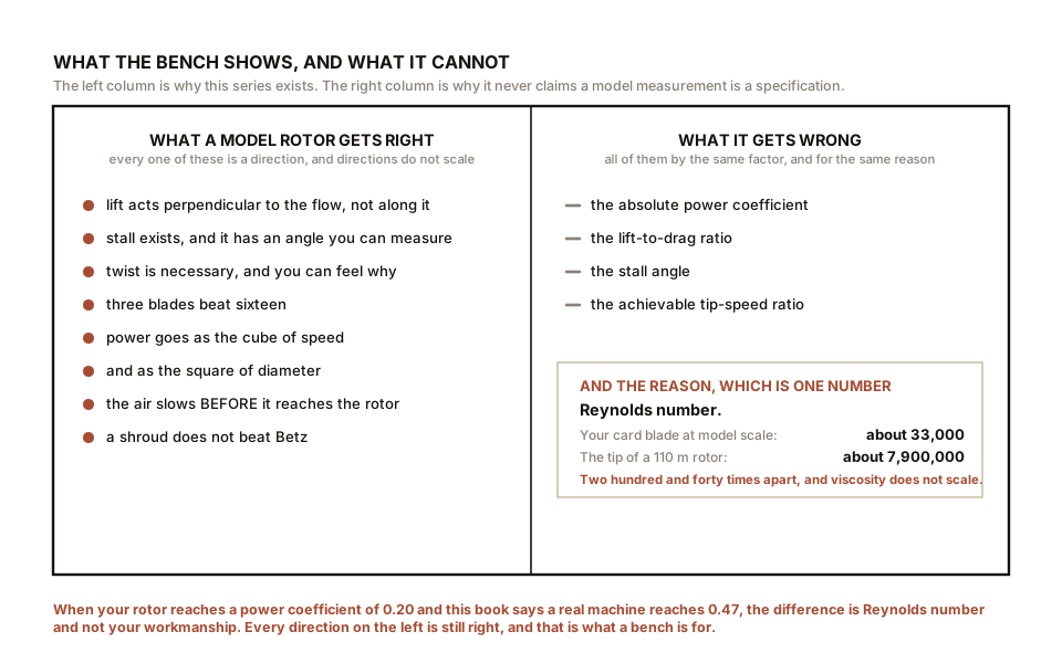
IN PLAIN ENGLISH: Almost everything a wind turbine does can be seen on a kitchen table for about fifty dollars. What cannot be seen there is how big the numbers get, because a model rotor runs at a Reynolds number a couple of hundred times too low. So the bench teaches you every mechanism and lies to you about every magnitude, and knowing which is which is most of what an engineer knows.
Section 3: The Ideas Worth Keeping
If everything else fades, these seven are the ones that transfer to other subjects, and several of them are not about wind at all.
One. Power goes as the cube of speed, and this is why siting beats hardware. A twenty percent windier site is worth 73 percent more energy. Every configuration in Chapters 7 and 8 spans a factor of about three in power coefficient; a bad site against a good one spans a factor of eight. You can lose more by choosing the wrong field than you can gain by choosing the right rotor, and the whole industry’s advertising is conducted as though the opposite were true.
Two. Lift beats drag by a factor of four, and it is exactly four. 16/27 against 4/27. The same algebra, the same peak at one third, and one number divided by the other. This is the single most useful thing in the book for judging a machine you have never seen, because you can classify almost anything as pushed or flying by looking at it.
Three. Betz applies to the frontal area of the device, not the part that turns. This one clause disposes of every shrouded, funnelled, concentrated or ducted claim in one sentence, and it disposes of them without needing to be rude about them, because the physics inside the duct is entirely real.
Four. An average is not a distribution, and when the thing you care about goes as a cube, the difference is nearly a factor of two. The energy pattern factor at an ordinary site is 1.91. This generalises far beyond wind: any time a quantity you care about depends nonlinearly on a variable quantity, the average of the variable is the wrong input, and using it will bias your answer in a predictable direction.
Five. Fatigue is exponential in load, and the exponent is about ten for a composite. So a ten percent load increase costs over half the life and a doubling costs a factor of a thousand. This is why turbulence destroys machines rather than merely slowing them, and it is why every design decision in Chapter 11 and Chapter 14 that looks like a sacrifice of energy is actually a purchase of life.
Six. A rated figure is an instantaneous quantity and a yield is an integral, and confusing them is the same error four times over. It is the small-turbine buyer watching his meter on a windy afternoon. It is the resource figure read as a yield figure. It is the capacity factor compared across different specific powers. It is the bladeless mast’s rated 100 W standing in for an annual harvest. All four are one mistake, and it is the mistake that the visible number is the useful number.
Seven. The binding constraint on a mature technology is very often not in the technology. Tower base diameter is set by bridge clearance. Onshore blade length is set by roundabouts. Tip speed is set by planning objections. None of those appear in any equation in this book and all of them decide what gets built, and looking for that constraint first is a habit worth carrying into any field.
Section 4: What This Volume Did Not Cover
Named plainly, because a book that pretends to completeness is not trustworthy on anything else.
Airborne wind energy. Kites, tethered wings and gliders flying crosswind on a line, harvesting the much stronger and steadier wind at 300 to 1,000 m (1,000 to 3,300 ft) with a tiny fraction of the material. The physics is genuine and interesting, several companies have flown prototypes for years, and none has reached commercial production. It gets no chapter here because there is no fleet to be honest about, and this book’s method needs measurements.
Detailed aeroelastic modelling. Chapter 11 said a blade bends usefully, and then stopped. The actual discipline is the coupled solution of the blade’s structural dynamics with the unsteady aerodynamics acting on it, including flutter, edgewise instability and the interaction between the pitch controller and the tower’s own motion. It is where modern rotor design actually happens and it needs numerical methods that no bench reaches.
Offshore floating foundations in any depth. Chapter 16 named the three families and drew them. The mooring analysis, the hull dynamics, the dynamic export cable, and the genuinely novel control problem of a rotor on a platform that pitches and heaves, were all left at the level of a paragraph.
Wind farm layout optimisation. Chapter 9 gave spacing rules of thumb. The real problem is a constrained optimisation over turbine positions with a wake model in the objective function, terrain and noise and setback constraints, and a directional wind distribution, and it is an active research field with real money in it.
Storage. Chapter 16’s fourth kind of intermittency, the multi-day low-wind event, is the largest unsolved problem in this subject, and this book pointed at it and moved on. Batteries, pumped hydro, hydrogen, thermal storage and the economics that decide between them are a volume of their own and not this one.
Blade end-of-life. A glass-epoxy blade is designed to resist degradation for twenty-five years, which is precisely the property that makes it hard to recycle. Thermoplastic resins, chemical recycling, cement kiln co-processing and the honest current answer of landfill are all real and all outside this book.
Acoustics and its perception. Chapter 6 gave the fifth-power law and Chapter 4 gave the mechanism. What decides planning applications is amplitude modulation and how humans respond to a rhythmic sound at low level, which is psychoacoustics rather than aerodynamics, and a decibel figure has never settled an argument about it.
Grid codes in detail, and market design. Chapter 16 described inertia, fault ride-through and curtailment. The actual documents that specify them run to hundreds of pages per jurisdiction and change every few years.
And two things this book deliberately did cover that a wind book often does not. Vertical-axis machines, in Chapters 7 and 8, all four of them, with numbers, because a book that shows the reader only the three-blade propeller has told them what to think rather than how to judge. And a chapter arguing against the product a reader might buy, in Chapter 15, because the physics that justifies a wind farm is the same physics that condemns a rooftop turbine, and applying it in only one direction would have been a choice.
ON THE BENCH: The capstone, with no equipment at all
Find a real turbine and derive its specification from what you can see and one web search. This takes an afternoon, needs nothing but arithmetic, and it is the exercise that proves the book worked.
Parts: a turbine you can see, or a photograph of one; the manufacturer’s data sheet, which is public for essentially every machine ever sold; a calculator. Cost: nothing. Time: an afternoon. Hazards: none, unless you go closer than the setback, which you should not.
Method. From the data sheet take only three numbers: rated power, rotor diameter and hub height. Everything else you derive.
- Swept area. π times the radius squared.
- Specific power. Rated power divided by swept area. Compare against Chapter 13’s table and place the machine in its era.
- Rated wind speed. Rearrange Chapter 1’s equation: it is the cube root of the rated power divided by 0.45 times ½ρ times the area. Then check it against the data sheet and see how close you got.
- Tip speed and tip-speed ratio. From the quoted rotor speed at rated, multiply by π times the diameter. Check it lands between 75 and 90 m/s (168 and 201 mph), and if it is much above that, ask whether the machine is offshore.
- Rotor torque at rated. Power divided by angular velocity. Note that it is measured in meganewton metres and think about the shaft.
- Thrust and tower base moment. Chapter 5’s thrust coefficient of 8/9 at optimal loading, times ½ρ times area times the square of rated wind speed, then multiplied by the hub height.
- Annual energy and capacity factor. Take the local mean wind speed from a public wind atlas, assume a Weibull shape factor of 2, and run Chapter 15’s bin-by-bin calculation against the published power curve.
What you should see: every derived number landing within ten or twenty percent of the manufacturer’s published value, and the ones that do not landing off for a reason you can name. If your rated wind speed comes out low, the machine’s real power coefficient is below 0.45 and you should ask why. If your capacity factor comes out high, check the wind atlas height against the hub height, because that is the commonest error and it is Chapter 9’s shear exponent taking its revenge one more time.
Better, if you have one: do this for three machines of the same rated power from different decades. The specific power will fall steadily and the capacity factor will rise steadily, and neither trend has anything to do with aerodynamics. Chapter 13 said that is where most of the last twenty years of improvement came from, and now you will have measured it.
ON THE BENCH: Build the best rotor you can, and account for the shortfall
The final experiment, and the point of it is to fall short and know exactly why.
Parts: everything you have used so far. Three blades made as carefully as you can manage, with camber, a rounded leading edge, a sharp trailing edge, and a twist that follows the inflow angles you measured in Chapter 4; a hub; your best generator; a variable load; an anemometer; a tachometer. Cost: nothing new. Time: a weekend, and take your time on the blades. Hazards: the fan, and balance the rotor properly before you run it hard.
Method: 1. Design the blades from the book rather than by eye. Choose a target tip-speed ratio of 5, which is realistic at model scale. At each of five stations along the blade compute the inflow angle from Chapter 4, subtract about 5 degrees for the angle of attack you want, and set the twist to that. 2. Measure the air speed, the swept area, the rotational speed and the electrical power at the best load you can find. 3. Compute your power coefficient: electrical power divided by ½ρAv³.
What you should see: something between 0.10 and 0.25, and if you get 0.25 with card blades you have done unusually well.
Now account for the shortfall, which is the whole exercise. The Betz limit is 0.593. A real machine gets 0.45 to 0.50. You got perhaps 0.18. Where did the difference go?
- Reynolds number, and it is the biggest item by far. Chapter 4 Section 6 put your blades at a Reynolds number of a few tens of thousands and a real blade at eight million, and the lift-to-drag ratio at 15 against 120. Chapter 6’s estimate says the drag loss is the tip-speed ratio divided by L/D, so at λ of 5 and L/D of 15 you have lost a third of your power to blade drag alone.
- Generator efficiency. A small brushed hobby motor run as a generator at part load is often 40 to 60 percent efficient, and you measured electrical power. That alone may account for another third.
- Tip losses, worse on a small rotor with a low aspect ratio.
- A non-uniform, swirling, spreading fan jet that is nothing like a uniform free stream.
Multiply those out and 0.18 is not a failure, it is the number the physics predicts. Which is the last and most important thing this book has to say about benches: a measurement you can account for is worth more than a measurement you are pleased with, and the ability to say where a missing sixty percent went is exactly the skill the whole series exists to build.
SLOW DOWN. Check Your Understanding: Here is a claim, of the kind you will meet. A company advertises a rooftop turbine with a shroud, described as a Fibonacci-optimised diffuser, rated at 1.5 kW, with a 1.2 m (47 in) rotor inside a 2.0 m (79 in) shroud mouth, and a claimed power coefficient of 0.68. It is offered at $4,000 installed. Take it apart, using only this book. Give yourself ten minutes before reading on.
There are five separate things wrong and you now have all five.
One, the power coefficient of 0.68 is above the Betz limit, so it has been computed against the rotor area. Compute it against the shroud mouth instead. The rotor’s area is 1.13 square metres (12.2 square feet) and the mouth’s is 3.14 square metres (33.8 square feet), a ratio of 2.78. So 0.68 divided by 2.78 is 0.24, which is a plausible number for a small shrouded rotor and is well under Betz. Nothing has been beaten. The gain was in the choice of divisor.
Two, the rated power implies a rated wind speed you should ask for. Working backwards, 1.5 kW at a device-referenced power coefficient of 0.24 through 3.14 square metres (33.8 square feet) needs
v³ = 1500 / (0.24 × 0.6125 × 3.14), which is about 3,250, so v is about 14.8 m/s, or 33 mph. That is a strong wind. On a roof.Three, the Fibonacci claim is decoration. Chapter 7: the golden ratio appears in plants as a divergence angle solving a packing problem, and there is no quantity in a rotor or a duct that plays that role. If the spiral geometry helps, it helps as curvature, and nobody has published a sweep of the growth ratio showing a peak at 1.618. The helix or the spiral may be real engineering. The number is a name.
Four, and this is the one that actually decides it: the site. Chapter 15. At a roof-level hub in a suburb the annual mean is likely 3 to 4 m/s (7 to 9 mph), inside a separated turbulent zone. The machine’s rated speed is 14.8 m/s (33 mph). The gap between those two numbers, cubed, is where the entire investment goes. Run the bin-by-bin calculation and the annual yield is likely in the low hundreds of kilowatt-hours, worth perhaps $30 to $60 a year on a $4,000 purchase.
Five, the comparison nobody offered you. $4,000 of solar panels is about 1.3 kW installed, producing roughly 1,800 kWh a year at a mid-latitude roof, which is five to ten times the energy, with nothing that turns and nothing bolted to the structure.
And notice what the demolition did not require. No laboratory, no test data, no accusation of dishonesty, and nothing the manufacturer did not publish themselves. Two areas, one cube root, a shear profile and a distribution. Every one of those came from a chapter of this book, and the whole thing takes ten minutes on the back of the advertisement.
That is what you now know.
Albert Betz is on the cover of this book, and he never built a wind turbine. He wrote down, in 1919, why every wind turbine that would ever exist had a ceiling, and he did it with conservation of mass, conservation of momentum, and a disc he refused to describe.
Thirty-eight years passed before anybody built a machine worth applying it to. The theory sat finished and unused while the industry it governed failed to exist, and then when the industry did arrive it arrived from a different direction entirely: from a Danish schoolteacher’s wind tunnel, from a boatyard’s glass fibre, from a certification scheme nobody wanted, and from the price of oil.
Which is the honest shape of most engineering. The elegant result and the working machine are usually separated by decades and by people who never meet, and the result is no less beautiful for having waited.
Go and stand under one. You can read it now.

Bench Degree
Get the degree without the diploma.
Learn the material, not how to pass the exam.