Bench Degree·ELECTROMAGNETISMchapter

Chapter 8: The AC Induction Motor
Cut one open. Inside the spinning part there is no winding, no magnet, no commutator, no connection of any kind. It is a lump of iron with aluminium bars cast through it, and about half the electricity generated on earth passes through machines like it.
Find a dead motor. A seized pool pump, a burned-out furnace blower, a bandsaw motor from a yard sale. They are free or nearly free, and the ones with a shorted winding are worthless to everybody except you.
Take the end bells off. Pull the rotor out.
There is nothing on it. No wires leave it. No brushes touch it. No slip rings, no contacts, no magnets. It is a stack of thin steel laminations with bars of aluminium or copper running through it lengthwise, and the bars are joined at each end by a solid ring of the same metal. That is all.
Etch one of those rotors in acid to dissolve the iron away and what is left is a cage: bars around a cylinder, joined top and bottom. It looks like something a Victorian would keep a squirrel in, which is exactly what it has been called for a hundred and thirty years.
Now hold the two pieces up. In the stator, coils of wire and 480 volts. In the rotor, an aluminium cage and no electrical connection to anything in the universe. The gap between them is about 0.4 mm (0.016 in) of air, and the only thing that ever crosses it is a magnetic field.
ON THE BENCH: Dissect a motor
Parts: any dead single-phase or three-phase induction motor, free to $20 at a scrapyard or from a repair shop’s discard pile; a socket set; a soft-faced mallet; a marker pen. Cost: nothing to $20. Time: an hour. Hazards: if the motor has a run capacitor, short its terminals with an insulated screwdriver before touching it: a capacitor can hold a lethal charge for days after the motor was last powered. Mark the end bell positions before you separate them or reassembly is guesswork. Edges of laminations are sharp. Method: unbolt the end bells, tap them free, slide the rotor out. Then look at four things and write down what you see. What you should see: One, the stator slots, and how many distinct coil groups there are. Count them and you have the pole count, which Chapter 7 told you sets the speed. Two, the rotor bars, usually skewed at a slight angle to the shaft rather than parallel with it. Three, the end rings joining all the bars. Four, the air gap, which you can measure with a feeler gauge and which will be startlingly small. Why the bars are skewed: parallel bars line up with the stator slots all at once, so the motor cogs and whines at a single loud tone. Skewing them spreads the effect out and quietens the machine. This is a manufacturing detail with an audible result, and once you know it you can hear the difference between a cheap motor and a good one. Then put it back together and keep it. A rotor and stator on the bench are the best teaching aids in this volume.
Section 1: Torque, in Four Steps
Chapter 7 left a magnetic field rotating in the stator at synchronous speed with nothing moving. Now put the cage in the middle of it.
Step one. The field cuts the bars, so voltage appears in them. The rotor is standing still and the field is sweeping past it at, say, 1,800 rpm. Each bar is a conductor in a changing field, which is Rule Two, and Chapter 4 gave the size of it: voltage proportional to field strength, bar length, and relative speed.
Step two. The bars are a closed circuit, so current flows. This is where the cage earns its shape. Each bar is joined to every other bar at both ends by the end rings, so the induced voltage has a path: down one bar, across the end ring, back up a bar on the other side. Large currents, hundreds of amps in a modest motor, circulating in a piece of cast aluminium with no terminals.
Step three. Current in a magnetic field feels a
force. This is Chapter 6’s F = BIL, applied to
bars instead of windings. The bar is carrying current, it is sitting in
the stator’s field, so it is pushed sideways. Every bar is pushed the
same way round. The rotor turns.
Step four. It turns in the direction that reduces the relative motion. Lenz’s law again, and here it becomes the engine rather than the brake. The induced current opposes the change that produced it, and the change is the field sweeping past the bars. The only way for the rotor to reduce that sweeping is to chase the field, and so it does.
That is the entire machine. Notice what it does not contain: no brushes, no commutator, no magnet, no rotor connections, and no starting arrangement of any kind in the three-phase case. Switch it on and it goes.
IN PLAIN ENGLISH: The stator makes a magnetic field that runs round in a circle. The rotor gets electricity induced into it, free, out of the air, by that circling field, exactly as your shaking tube in Chapter 1 got electricity induced into it. Then the rotor’s own current gets pushed on by the field that made it, and the push is always in the direction of the chase. The rotor is a generator and a motor at the same time, and it never has to be told anything.
Section 2: Slip, and Why the Rotor Can Never Catch Up
Follow the chase to its logical end.
Suppose the rotor did catch the field and turn at exactly 1,800 rpm. Then the field would no longer be sweeping past the bars, because they would be travelling together. No relative motion means no changing flux, which means no induced voltage, which means no current, which means no force. The moment it caught up, everything that was driving it would vanish.
So it cannot catch up, and it does not want to. It settles at a speed a little below synchronous, at whatever gap produces exactly the torque the load demands. That gap has a name.
slip = (Ns - Nr) / NsNs is the synchronous speed, Nr is the actual rotor speed. Slip is usually given as a percentage.
Now put the nameplates from Chapter 7 into it. A four-pole 60 Hz motor has a synchronous speed of 1,800 rpm. Its nameplate says 1,750 rpm at rated load.
slip = (1800 - 1750) / 1800 = 0.028 = 2.8%That is why no nameplate in the world says 1,800 rpm. The rated speed is the speed at full rated load, and full load requires slip, and 2.8 percent of 1,800 is 50 rpm.
Run the same motor with nothing attached and it will read about 1,795 rpm: 0.3 percent slip, just enough to overcome its own bearings and windage. Hang a load on it and it slows, the slip grows, the induced current grows, the torque grows to match the load, and it stops slowing. Hang a heavier load and it slows further and pushes harder. There is no controller doing this. There is no sensor. It is Faraday’s law and Lenz’s law arranging a self-regulating machine between them.
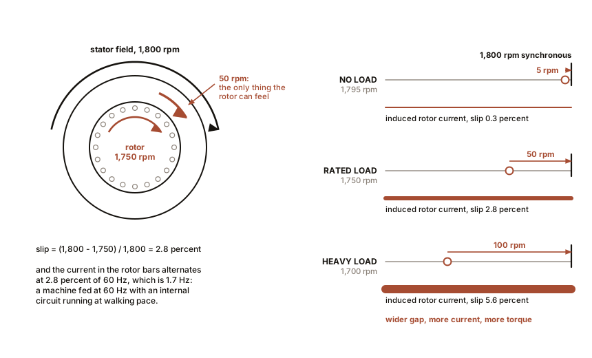
There is a lovely detail hiding here. The frequency of the current actually flowing in the rotor bars is the slip times the supply frequency. At 2.8 percent slip on 60 Hz, the rotor’s own currents are alternating at 1.7 Hz. A machine fed at 60 Hz has an internal circuit running at walking pace, and the frequency changes with the load.
ON THE BENCH: Measure slip on a running motor
Parts: any induction motor you can run safely, salvaged or $15 to $75; a non-contact optical tachometer, $15 to $30; a clamp ammeter if you have one; something to load the shaft with, such as a fan blade, a grinding wheel, or a rag pinched round the shaft. Cost: $15 to $105. Time: 45 minutes. Hazards: rotating shaft. Tie hair back, no loose sleeves, no gloves near the shaft. Put a reflective sticker on the shaft for the tachometer rather than holding anything against it. Method: read the nameplate and compute the synchronous speed. Measure the free-running speed. Then load it progressively and measure again at each step, recording current if you can. What you should see: free running within half a percent of synchronous. Loaded, the speed falls by tens of rpm and the current climbs. Plot slip against current and you get a line that is almost straight over the normal working range. The number that surprises people: the total speed variation from no load to full load on a 1,800 rpm machine is about 50 rpm, under three percent. An induction motor is a nearly constant-speed machine that nevertheless regulates its own torque perfectly, and it does both with the same mechanism. If your tachometer reads a multiple of the true speed: it is triggering on the shaft key or a mark you did not intend. Use one clean reflective strip.
Section 3: The Torque and Slip Curve, and Where the Motor Lives
Plot torque against slip from zero to one and you get a shape worth memorising.
From zero slip the torque rises almost in a straight line. This is the working region, and every industrial motor spends its life in the first three to five percent of it. The slope is steep, which is what makes the machine stiff: a large change in torque costs a small change in speed.
The line keeps rising, bends over, and reaches a maximum somewhere around 15 to 25 percent slip. That peak is the breakdown torque, and for a standard general-purpose motor it is 200 to 300 percent of the rated torque. It is the most the machine can ever produce, and it is the wall that a jammed conveyor hits.
Beyond the peak the torque falls as slip increases further. This region is unstable and it is where motors die. If the load ever exceeds breakdown torque, the motor slows past the peak, its torque drops, so it slows more, so its torque drops more, and it slams down to a stall in a fraction of a second with locked-rotor current pouring through the windings. The overload relay in the starter exists for exactly those next few seconds.
At the far end, at 100 percent slip, the rotor is stationary. That is the moment you close the contactor, and it deserves its own section.
Section 4: Starting Current, and Why Big Motors Get Starters
At the instant of switch-on the rotor is still, the field is sweeping past the bars at full synchronous speed, and the induced voltage in the rotor is at its maximum. The current that follows is enormous.
Locked-rotor current is typically six to eight times the full-load current. A 10 HP motor drawing 14 A at full load will pull 85 to 110 A for the second or two it takes to run up. Nobody minds on a 10 HP machine. On a 500 HP mine hoist, drawing several thousand amps out of a distribution network dips the voltage for everyone on the feeder and makes the lights blink across a town.
So large motors are started with something between them and the line. Three arrangements you will meet:
Star-delta. The stator windings are connected in star for starting, which puts less voltage across each winding, then switched to delta once the motor is up to 75 or 80 percent of speed. Current during starting drops to about a third. The cost is that starting torque also drops to about a third, so this only works for loads that start light: fans, unloaded compressors.
Soft starter. Back-to-back thyristors ramp the applied voltage up over a few seconds. Smooth, adjustable, and cheap enough that it has largely replaced star-delta.
Variable frequency drive. The complete answer, and the one that changes what the machine is.
ON THE BENCH: Reverse a three-phase motor with two wires
Parts: a three-phase motor and a three-phase supply, or far more likely a small variable frequency drive that makes three-phase from a single-phase outlet, about $60 to $90 for a 1/2 HP unit; a screwdriver. Cost: $60 to $90 for the drive, plus $15 to $75 for the motor. Time: 20 minutes. Hazards: isolate and lock out the supply before opening any terminal box, and wait for the drive’s DC bus capacitors to discharge, which is typically five minutes and is printed on the case. This is the one experiment in this volume where getting it wrong is genuinely dangerous. If you have never worked inside a motor terminal box, do this one beside somebody who has. Method: run the motor and note which way the shaft turns, looking at the shaft end. Isolate. Swap any two of the three motor leads in the terminal box. Restore and run again. What you should see: it turns the other way. That is all it takes, and it works with any two of the three. Why: swapping two phases changes the order in which the three coil groups reach their peaks, from A-B-C to A-C-B. The rotating field of Chapter 7 rotates the other way, and the rotor, which does nothing but chase, chases the other way. What this proves about the machine: the motor contains no concept of forward. It has no gearbox, no clutch, no reversing contactor, nothing internal that cares. Direction lives entirely in the sequence of the supply, which is why an electric car’s reverse gear is a line of software and why a brushed motor needs a physical switch to do the same job.
Section 5: The Variable Frequency Drive, Which Finishes the Idea
Chapter 7 gave the formula Ns = 120f / P and said that
the supply frequency is the master clock. For seventy years that clock
was fixed at 60 or 50 Hz by the grid, and an induction motor was
therefore a fixed-speed machine. If you wanted a different speed, you
fitted a gearbox, a belt, or a throttling valve, and threw away energy
for the privilege.
A variable frequency drive takes AC from the wall, rectifies it to DC, and then synthesises fresh three-phase AC at whatever frequency you ask for, by switching the DC on and off thousands of times a second with power transistors. The motor windings smooth the switching and see something close to a sine wave.
at 6 Hz,   a 4-pole motor's synchronous speed is 180 rpm
at 30 Hz,  it is 900 rpm
at 60 Hz,  it is 1,800 rpm
at 120 Hz, it is 3,600 rpm
One rule governs the voltage: the drive must raise voltage in step with frequency, holding the ratio roughly constant, because Chapter 5 showed that flux depends on volts divided by frequency and a core driven at low frequency with full voltage saturates. Every drive does this automatically, and the ratio has a name, volts per hertz.
The consequence is a motor with full torque available from a standstill and a smoothly adjustable speed, with no brushes, no gearbox and nothing to wear. Fit one to a pump that was previously throttled by a valve and the energy saving is commonly 30 to 50 percent, because you are no longer pumping hard against a deliberate restriction.
This is the machine that runs the modern world. Roughly half of all electricity generated on earth is consumed by electric motors, and the great majority of those are induction motors. Your furnace blower, your well pump, every conveyor in every warehouse, and the traction motor in a considerable number of cars.
SLOW DOWN. Check Your Understanding: An induction motor’s rotor is an aluminium cage with no connections. Aluminium is a worse conductor than copper, by about forty percent. So why are the great majority of squirrel cages cast in aluminium rather than copper, when the manufacturer could obviously make a better conductor? Predict before reading on.
Cost and casting are part of it, but the real answer is that more rotor resistance is sometimes exactly what you want, and the designer chooses it deliberately.
Recall Section 3. The breakdown torque does not depend on the rotor’s resistance at all; what the resistance sets is the slip at which breakdown torque occurs. Higher rotor resistance moves the whole peak toward higher slip, which means toward lower speed, which means more torque available at startup. A motor for a crane or a conveyor that has to break away under load is deliberately built with high-resistance rotor bars, accepting more slip and slightly lower efficiency at full speed in exchange for muscle at the bottom.
This is why motors are sold by design letter rather than only by horsepower. A Design B motor is the general-purpose compromise. A Design D motor has high-resistance bars, up to 13 percent slip at rated load, and enormous starting torque, and it is what you bolt to a punch press. The rotor is not a wire. It is a tuning knob that gets cast in place once and never adjusted again, and choosing it is most of the art of specifying a motor.
The physics is now complete. Two rules, one rotating field, one cage, and a machine that beats the commutator in every dimension. What remains is the commercial fight over which kind of current would flow in the wires, and that fight was uglier and more consequential than the engineering deserved.

Bench Degree
Get the degree without the diploma.
Learn the material, not how to pass the exam.