Bench Degree·ELECTROMAGNETISMchapter

Chapter 7: The Rotating Magnetic Field
Two coils, sitting still, bolted down, nothing moving anywhere. Put a compass between them and the needle spins like a top. Once you have seen that, the motor builds itself.
Start with the cheating version, because it makes the target obvious.
Chuck a neodymium magnet in a cordless drill, so that it spins about its own diameter rather than about its axis. Hold a small compass 25 mm (1 in) above it and pull the trigger gently.
The compass needle chases the magnet round. Slowly at first, then it locks in and spins, following the field. Now swap the compass for a small aluminium disc on a pin, a coin-sized one cut from a drinks can, and it will turn too, which is startling, because aluminium is not magnetic and the disc is not being pulled toward anything.
There is your motor. It has one fatal flaw: to make that field rotate, something already had to be rotating. You used a drill. In 1882 the drill would have been a brushed DC motor with the two carbon blocks of Chapter 6, and you would have gained nothing.
The question that made a career is this. Can you make a magnetic field rotate without rotating anything at all?
ON THE BENCH: A rotating field the honest way, with a drill
Parts: a neodymium magnet, about $2; a cordless drill; a cheap button compass, about $4; a disc about 25 mm (1 in) across cut from an aluminium drinks can, balanced on a pin or a needle. Cost: about $6. Time: 10 minutes. Hazards: a magnet thrown from a drill chuck is a projectile. Grip it properly, wear eye protection, keep the speed low. Method: hold the compass, then the disc, a short distance above the spinning magnet. What you should see: the compass locks to the magnet’s rotation and follows it exactly, at the same speed. The aluminium disc also turns, but slower than the magnet, always slower, and it speeds up if you bring it closer. Write that observation down. It is the whole of Chapter 8, and the gap between the two speeds has a name. Then: try a copper disc instead. It drags harder, for the reason Chapter 4’s pipe gave you.
Section 1: Budapest, February 1882
Nikola Tesla was twenty-five and working for a telephone company. He had spent two years at the Technical College in Graz being told, by a professor demonstrating a Gramme dynamo, that a motor without a commutator was a contradiction in terms, and had said out loud in the lecture that he thought otherwise. He had been thinking about it since.
His own account, written thirty-seven years later, has him walking in the city park at sunset, reciting Goethe, when the arrangement arrived complete. He drew it in the dirt with a stick. Whether the moment was as clean as he remembered it cannot be checked, and the story has been retold so often that it has worn smooth. What can be checked is the hardware, and the hardware is not in doubt.
Nor was he alone. Galileo Ferraris in Turin worked out the same principle independently and published it in 1888, and there is no evidence either man knew of the other’s work. Two people finding the same thing within a few years is the usual pattern in engineering history, and it is a mark of an idea whose time had come rather than of a theft.
Here is what they found.
Section 2: Two Coils, One Quarter Turn Apart in Time
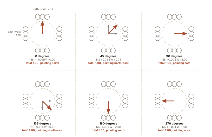
Set two coils at right angles to each other, north-south and east-west, both aimed at the same empty space in the middle.
Feed the north-south coil with alternating current. Its field points north, then fades to nothing, then points south, then fades, sixty times a second. On its own it is a field that pulses back and forth along one line. A compass in the middle would shudder and stay put.
Now feed the east-west coil with alternating current at the same frequency, but delayed by a quarter of a cycle. When one coil is at its peak, the other is at zero. When one is at zero, the other is at its peak.
Follow the pair around one cycle. Call the strength of each coil at full drive one unit.
| Point in the cycle | North-south coil | East-west coil | Where the total field points |
|---|---|---|---|
| 0 degrees | +1 | 0 | north |
| 45 degrees | +0.71 | +0.71 | north-east |
| 90 degrees | 0 | +1 | east |
| 135 degrees | -0.71 | +0.71 | south-east |
| 180 degrees | -1 | 0 | south |
| 270 degrees | 0 | -1 | west |
| 360 degrees | +1 | 0 | north again |
Read the right-hand column downward. The combined field has swung all the way round the compass, in one electrical cycle, and nothing moved.
Then check the strength, which is the part that makes it a machine rather than a curiosity. At 45 degrees both coils are at 0.71, and by Pythagoras the total is the square root of 0.71 squared plus 0.71 squared, which is 1.00. At 0 degrees one coil is at 1 and the other at 0, and the total is 1.00. The field does not merely rotate, it rotates at constant strength. A compass needle in the middle is not shaken; it is led round, smoothly, by a field of unvarying size.
IN PLAIN ENGLISH: Two people pushing a swing, one from the front and one from the side, taking turns in a strict rhythm. Neither of them moves round the swing, but the direction of the push does, and it goes right round the circle four times a second. The rhythm is what rotates. Feed a coil a delayed copy of what you fed its neighbour, and the delay becomes rotation.
ON THE BENCH: A rotating field with nothing moving
Parts: two identical coils of 300 to 400 turns of 26 AWG magnet wire on 25 mm (1 in) forms, about $10 of wire; a 16 V AC doorbell or thermostat transformer, about $14; one non-polarised capacitor, 2 to 10 microfarads at 100 V or better, about $3; a button compass; a wooden board; a series resistor of 100 ohms to keep the currents modest. Cost: about $30. Time: an hour. Hazards: the transformer’s input side stays in its enclosure. Everything you handle is at 16 V AC. The coils warm up; run in short bursts. Method: mount the two coils at right angles on the board, aimed at a gap in the middle about 30 mm (1.2 in) across, and put the compass in the gap. Wire coil A directly across the 16 V AC through the resistor. Wire coil B across the same 16 V AC through the capacitor, which shifts its current in time relative to coil A. Switch on. What you should see: with only coil A energised the needle jitters violently and picks a line. With both energised the needle swings decisively to one orientation and, if the phase shift is close enough to a quarter cycle, it will rotate or hunt round in one direction. Swap the two wires on coil B and it goes the other way. That single observation is the answer to one of Chapter 1’s promises, three chapters early. If the needle only jitters: your capacitor is giving too little phase shift. Try a larger value. A compass needle is also badly suited to following 60 Hz, so what you are really watching is which way it drifts and settles; a small aluminium disc on a pin is a better indicator, because it responds to the average rotation rather than the instant. Better, if you have one: two channels of a stereo amplifier fed a low-frequency stereo tone whose two channels are a quarter cycle apart, at 5 or 10 Hz, will drive the coils slowly enough to watch the needle walk round one step at a time.
Section 3: Why Three Phases Beat Two
Tesla’s first patents covered two-phase systems, and two-phase machines were built and sold and ran the Chicago World’s Fair. Almost every power system on earth is now three-phase, and there are three good reasons.
Constant power. In a two-phase system, add up the instantaneous power in both phases and the total pulses. Three phases spaced 120 degrees apart sum to a total that is dead constant, instant by instant. A three-phase motor therefore receives a smooth flow of energy, which means smooth torque, less vibration, and quieter bearings.
Fewer wires for the same power. In a balanced three-phase system the three currents sum to zero at every instant, so the return path carries nothing and can be omitted entirely. Three wires carry three phases. Delivering the same power as single-phase costs about 75 percent of the copper. On a transmission line running for hundreds of kilometres, saving a quarter of the copper is not a refinement, it is the project’s budget.
Self-starting, in both directions. A two-phase field rotates, but the quarter-cycle shift is awkward to generate: you need either a specially wound generator or a capacitor that only approximates the shift and drifts with load. Three phases come naturally out of a generator with three sets of windings spaced 120 degrees around the stator, exactly, forever, with nothing to drift.
And one consequence you will use with your hands in the next chapter. Swap any two of the three wires and the field rotates the other way. Not two of four, not a rewiring, not a reversing switch. Two wires, in a terminal box, thirty seconds.
Section 4: Synchronous Speed, and Reading It Off a Nameplate
The field rotates once per electrical cycle in the simplest possible stator, the one with two magnetic poles. Wind the stator with two sets of coil groups instead of one, giving four poles, and the field only gets halfway round the machine per electrical cycle, so it turns at half the speed.
That gives the most useful formula in industrial electrics:
Ns = 120 x f / PNs is the synchronous speed in revolutions per minute, f is the supply frequency in hertz, and P is the number of poles. The 120 is not physics, it is 60 seconds a minute times 2 poles per pole-pair.
| Poles | At 60 Hz | At 50 Hz |
|---|---|---|
| 2 | 3,600 rpm | 3,000 rpm |
| 4 | 1,800 rpm | 1,500 rpm |
| 6 | 1,200 rpm | 1,000 rpm |
| 8 | 900 rpm | 750 rpm |
| 12 | 600 rpm | 500 rpm |
The supply frequency is the master clock and the pole count is the gear ratio. Nothing else in the machine sets its speed: not the voltage, not the load, not the size. A four-pole motor on 60 Hz turns at 1,800 rpm and there is no adjustment.
Which raises the obvious question, and the answer is Chapter 8 and then Chapter 16. If speed follows frequency, then a box that can make any frequency you like can make any speed you like. That box exists, it costs about $60 for a small one, and it is why an electric car has one gear.
ON THE BENCH: Read the pole count off a motor you already own
Parts: any AC motor with a legible nameplate. A furnace blower, a pool pump, a bench grinder, a compressor, a bandsaw. Cost: nothing. Time: 15 minutes. Hazards: read the plate with the machine switched off at the breaker if you need to move anything to see it. Method: find the rated speed and the frequency. Then work backwards: whichever synchronous speed in the table above sits just above the rated speed is your machine’s, and the poles come with it. What you should see: a plate reading 1,725 rpm or 1,750 rpm at 60 Hz is a four-pole machine with a synchronous speed of 1,800 rpm. A plate reading 3,450 rpm is two-pole, synchronous 3,600 rpm. A plate reading 1,140 rpm is six-pole, synchronous 1,200 rpm. The question this raises: why is the rated speed always below the synchronous speed, and always by a few percent rather than by a round number? No nameplate in the world says 1,800 rpm. The next chapter is that question, and it is the whole mechanism of the machine.
Section 5: What the Patents Actually Claimed
Tesla filed the foundational application on 12 October 1887 and it issued as US Patent 381,968, “Electro Magnetic Motor,” on 1 May 1888, alongside a suite of related filings covering the generator, the transformer arrangements and the distribution system.
On 16 May 1888 he read a paper to the American Institute of Electrical Engineers at Columbia University, “A New System of Alternate Current Motors and Transformers.” It described the whole thing as a system rather than as a device: polyphase generators, polyphase motors, transformers, and how they fitted together. The full text is in Thomas Commerford Martin’s 1894 collection of Tesla’s work, which is out of copyright and freely readable.
Within weeks George Westinghouse’s people were in touch. The terms were $60,000 in cash and stock, 150 shares of Westinghouse Electric, and a royalty of $2.50 per alternating-current horsepower on every motor sold. Tesla went to Pittsburgh for about a year to help turn laboratory models into manufacturable drawings, and the collaboration was not frictionless: Westinghouse’s engineers had standardised on 133 Hz for lighting, which is a poor frequency for motors, and the argument that followed is part of why North America settled on 60 Hz.
What the patents claimed is precisely what you built on the board with two coils and a capacitor. Not free energy, not a new force, not a suppressed secret. A method of producing a rotating magnetic field from stationary windings by feeding them currents displaced in time, and a machine to exploit it.
SLOW DOWN. Check Your Understanding: A rotating magnetic field is not a magnet. Nothing is orbiting, no iron is moving, and there is no object in the middle of the stator at all. So what, physically, is going round? Answer before reading on.
The pattern is going round, and nothing else. The same thing happens on a theatre marquee where a chasing light appears to travel along the sign: no bulb moves, and each one merely switches on after its neighbour. The apparent motion is real in the sense that it can be timed and photographed, and it is not made of anything.
Here is why that matters rather than being a philosophical aside. A pattern has no mass, so a rotating field can be started, stopped or reversed instantly, at no mechanical cost. It cannot fly apart at high speed, it does not need bearings, and it does not wear. Every disadvantage of the commutator in Chapter 6 came from the fact that the switching was done by an object. Here the switching is done by the arithmetic of three sine waves, and arithmetic does not need brushes.
There is one thing left to build. The field is turning. Now something has to be dragged round after it, and the elegant part is that the thing dragged round needs no electrical connection to anything at all.

Bench Degree
Get the degree without the diploma.
Learn the material, not how to pass the exam.