Bench Degree·ELECTROMAGNETISMchapter

Chapter 6: The Brushed DC Motor, What Tesla Had to Beat
One battery, one screw, one magnet, and a scrap of wire. Ten seconds after you touch them together you will have built a motor, and you will also have built its central weakness.
Take an AA battery, a coarse steel wood screw about 30 mm (1.2 in) long, a neodymium disc magnet, and a 150 mm (6 in) piece of wire.
Stick the magnet to the head of the screw. Hang the screw point-up from the flat negative end of the battery, where the magnet will grab and hold it. It dangles there, magnet at the bottom.
Now touch one end of the wire to the battery’s positive terminal and brush the other end lightly against the edge of the hanging magnet.
The screw spins. Immediately, and fast, several thousand revolutions a minute, held by nothing but magnetism, and it keeps going as long as you keep contact.
You have just built a motor with three components and no switch, no brushes, no commutator, no windings. It is called a homopolar motor, it was Faraday’s first one in 1821, and it is the entire principle of every electric motor ever built with everything unnecessary stripped away.
ON THE BENCH: The ten-second motor
Parts: one AA or AAA alkaline cell; one coarse steel screw 25 to 40 mm (1 to 1.6 in) long; one neodymium disc magnet 10 to 12 mm (0.4 to 0.5 in) across; 150 mm (6 in) of any wire. Cost: about $3, and nothing if you have a junk drawer. Time: 10 seconds once you have the parts. Hazards: you are shorting a battery through a fraction of an ohm. The wire gets hot, the battery gets hot, and it will run flat in a minute or two. Touch and release, do not hold it. Never do this with a lithium cell, which can vent or catch fire. What you should see: the screw spins in one direction. Turn the magnet over and it spins the other way. Reverse the battery and it also reverses. Two reversals cancel: turn both over and it spins the original way again. If it does not spin: you are touching the magnet’s flat face instead of its edge, or your contact is too firm and is braking it. Brush the very rim. Where the force is: current flows down the screw, sideways out through the magnet’s body, and back through the wire. The sideways part is a current crossing a magnetic field, and that is the whole of the next section.
Section 1: F = BIL, the One Equation Motors Run On
Rule One says a current makes a magnetic field. Set that current’s field beside another magnet’s field and the two push on each other. Written as a force on the wire:
F = B x I x LForce equals the field strength, times the current, times the length of wire sitting in that field. Force comes out in newtons when B is in tesla, I in amps, and L in metres.
The direction is at right angles to both, which is the part that feels wrong the first six times. The current runs one way, the field runs another, and the wire is shoved in the third direction, perpendicular to both of them. Point the fingers of your right hand along the current, curl them toward the field, and your thumb points where the wire goes.
Now put a number in it, because the number is instructive.
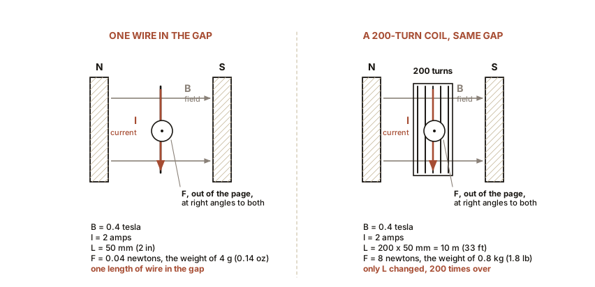
Take a good neodymium field of 0.4 tesla, a healthy 2 amps, and 50 mm (2 in) of wire in the gap.
F = 0.4 x 2 x 0.05 = 0.04 newtonsForty millinewtons. That is the weight of four grams (0.14 oz), a small coin. One wire in a strong field with real current produces a contemptible force, and that single fact dictates the shape of every motor in existence.
There are only three terms to attack. Raise B, and you are limited by saturation from Chapter 5 and by what magnets cost. Raise I, and you are limited by the heat the copper can shed. Raise L, and there is your answer: use more wire. A coil of 200 turns puts 200 lengths of wire in the same gap and multiplies the force by 200. Wind several coils around a rotor and put the whole thing in a tight iron circuit so that almost no field is wasted, and forty millinewtons becomes a hand drill.
Section 2: The Commutator, Looked at Slowly
A coil in a magnetic field is pushed one way on one side and the other way on the other side, so it turns. Good. It turns a quarter revolution, then another, and then it reaches the point where it is lying flat across the field with its two sides swapped over.
At that instant, if the current keeps flowing the same way, the force reverses and tries to turn the coil back. The motor would rock and stop.
So the current in the coil must reverse at exactly that moment, every half revolution, forever. The commutator is the machine that does the reversing, and it is a switch made of the motor’s own geometry.
The coil’s two ends terminate on a copper ring split into segments, mounted on the shaft so it turns with the coil. Two carbon blocks, the brushes, are held against the ring by springs. As the shaft turns, each brush crosses from one segment to the next at precisely the moment the coil goes flat, and the connection flips. The coil’s current reverses. The force keeps pushing the same way round.
Chapter 2 said a DC generator is an AC machine with a mechanical rectifier bolted on. Here is the same statement from the other side: a brushed DC motor is an AC motor whose alternating current is manufactured inside the machine by a switch that rubs.
Real motors use more than two segments, typically 3, 5, 7 or more, with a coil to each pair, so that some coil is always well positioned and the torque does not pulse badly. An automotive starter has dozens.
IN PLAIN ENGLISH: The magnet can only ever pull the coil toward one position. To get continuous rotation, something has to keep moving the goalposts. The commutator moves the goalposts, twice per revolution, by swapping which way the electricity goes round the coil. It is a switch that has to operate a hundred times a second, forever, and it is made of a carbon block sliding on spinning copper.
ON THE BENCH: Build a motor with a commutator you can see
Parts: 1.5 m (5 ft) of 26 AWG magnet wire; two large steel paper clips; a AA cell and a holder, or tape; a neodymium magnet; sandpaper; a rubber band. Cost: about $5. Time: 25 minutes. Hazards: the coil warms. Short bursts. Method: wind 25 turns of wire around a AA cell to make a neat loop about 14 mm (0.55 in) across, then slide it off. Leave 25 mm (1 in) of wire straight out on each side as an axle, exactly opposite each other, so the loop is balanced. Now the trick: scrape the enamel off one axle all the way round, and off the other axle on one side only. Bend the paper clips into hooks, tape them to the battery terminals, rest the axles in the hooks, and put the magnet directly under the coil. What you should see: flick the coil and it spins up and runs. The half-scraped axle is your commutator: for half of each revolution it conducts and the coil is pushed, and for the other half it insulates and the coil coasts through the awkward part on its own momentum. If it will not start: it almost never self-starts, and that is not a fault. Flick it. If it stops dead in one place every time, your scraped half is 90 degrees out of position; rotate the wire in your fingers and try again. What you have proved: timing is everything in a commutated machine. The switch must operate at the right angle, not merely at the right rate, and the whole art of building these motors is getting the brush position right.
Section 3: Back-EMF, Which Is Lenz Wearing a Motor’s Coat
Take any small DC motor out of a broken toy. Connect a multimeter across its terminals, set to DC volts, and spin the shaft with your fingers.
The meter reads a voltage. Spin it faster and the voltage rises. Spin it the other way and the sign flips.
That is not a surprise by now: you are moving coils past magnets, which is Rule Two, which is Chapter 1’s tube. Every motor is a generator when you turn it.
The consequence is the important part. When a motor is running under power, it is generating at the same time. The coils are moving in a field, so they produce a voltage, and by Lenz’s law that voltage opposes the supply driving them. It is called the back-EMF, and it grows in proportion to speed.
Now the arithmetic. The current in the motor is set by the difference between the supply and the back-EMF, divided by the winding resistance:
I = (V_supply - V_back) / R_windingFollow a motor through a start. At the instant you switch on, the shaft is not moving, the back-EMF is zero, and the current is limited by nothing except the winding resistance, which is tiny. That is stall current, or inrush, and it can be twenty times the running current. As the motor speeds up, the back-EMF climbs, the difference shrinks, and the current falls. At full speed with no load, the back-EMF has climbed to nearly the supply voltage and the current has fallen to almost nothing.
This is why a drill screams when free and grunts when you lean on it, and why the lights in an old house dip when the refrigerator starts.
ON THE BENCH: Measure inrush and back-EMF on a small motor
Parts: any small brushed DC motor, 12 V rated, salvaged or about $6; a bench supply or a 12 V battery; a multimeter that can read DC amps; an optical tachometer if you have one, about $15. Cost: $6 to $25. Time: 30 minutes. Hazards: keep fingers and hair away from the shaft. Stalling the motor for more than a second or two will cook the winding. Method: measure the winding resistance with the shaft still. Then run the motor free and measure current. Then load it by pinching the shaft with a rag and watch the current climb. What you should see, on a typical small 12 V motor: winding resistance around 1.5 ohms. Free running current 0.2 to 0.4 A. Stall current 12 divided by 1.5, which is 8 A, or about twenty-five times the free running figure. Watch it on the meter as you pinch. Then do the sum that closes the loop. Free running at 12 V with 0.3 A through 1.5 ohms means only 0.45 volts is being dropped in the copper. The other 11.55 volts is back-EMF. The motor is generating almost as hard as the supply is pushing, and the tiny difference between them is all the current there is.
Section 4: The Speed and Torque Curve, and What It Means for Real Work
Put those relationships together and the brushed DC motor’s behaviour comes out as a straight line.
Torque is proportional to current, from F = BIL. Current
is proportional to the gap between supply voltage and back-EMF. Back-EMF
is proportional to speed. So:
Torque falls in a straight line as speed rises. Maximum torque at zero speed, zero torque at full speed, a straight line between.
That line has three points worth naming.
Stall. Zero speed, maximum torque, maximum current, and zero mechanical output because nothing is moving. Every watt going in becomes heat in the winding. A motor held stalled destroys itself in seconds to minutes.
Free run. Maximum speed, zero torque, minimum current. Also zero useful output, for the opposite reason: plenty of motion, nothing being pushed.
Halfway. Half of stall torque at half of free speed. This is where a brushed DC motor makes its maximum mechanical power, and it is a straightforward consequence of a straight-line torque curve: power is torque times speed, and the product of two numbers summing to a constant peaks when they are equal.
Peak efficiency sits somewhere else again, nearer 15 to 20 percent of stall torque, because the copper losses grow as the square of current while the useful output grows only in step with it. Maximum power and maximum efficiency are different operating points, and choosing between them is what gearing is for.
SLOW DOWN. Check Your Understanding: A brushed DC motor free-runs at 8,000 rpm on 12 V. You need it to turn at 4,000 rpm, so you halve the supply to 6 V. Does it now produce half the torque, the same torque, or something else? Predict before reading on.
At 4,000 rpm on 6 V it produces almost exactly the same torque it would have produced at 4,000 rpm on 12 V, which is roughly half of its stall torque, and this catches nearly everyone. The reason is the equation in Section 3: torque depends on the difference between supply and back-EMF, not on either alone. At 6 V the back-EMF at 4,000 rpm is about 6 V, so the gap is small and the torque is small. But at 12 V the machine will not sit at 4,000 rpm unless a load is holding it there, and to hold it there the load must be supplying the torque that the large 12 V gap is producing.
What actually changed is not the torque available at a speed, it is where the motor settles. Halving the voltage halves the free speed and halves the stall torque, sliding the whole straight line down without changing its slope. That slope, torque per volt of gap, is fixed by
B x Land the winding resistance, which is to say by the iron and copper. Voltage sets where on the line you sit. The line itself is built into the machine.
Section 5: What Was Wrong With It
This machine ran the industrial world for fifty years and every objection to it comes back to the same two carbon blocks.
They spark. Every time a brush crosses a gap between segments it breaks a current in an inductive coil, and breaking current in an inductor makes a voltage spike, which jumps the gap as an arc. That arc erodes copper and carbon and throws radio interference across the whole spectrum. Hold an AM radio near a running hand drill and listen to the noise.
They wear. Brushes are consumables. Industrial DC motors had scheduled brush changes, and the commutator itself had to be resurfaced. In a factory with a thousand motors, that is a permanent department.
They limit voltage and speed. The higher the voltage, the harder the arcing at each transition. The higher the speed, the more transitions per second and the more heat in the contact. Both ceilings sit uncomfortably low.
They cannot be sealed. Carbon dust is conductive and abrasive, and it needs airflow to clear. So a brushed motor cannot easily be closed, which rules it out of anything flammable, wet or dirty.
And, crucially in the 1880s, they were the reason a motor was a DC device. A commutated machine wants steady current in one direction to reverse mechanically. Feed the ordinary shunt-wound kind with alternating current and it does nothing useful. So a world of brushed motors was a world that needed DC delivered to every factory floor, and Chapter 3 has already shown what delivering DC across a city costs.
There is one exception worth knowing, because you own several. Wire the field coils in series with the rotor rather than in parallel, and when the supply reverses, both the field and the rotor current reverse together. Two reversals cancel, exactly as they did with the screw and the magnet in the opening, and the torque stays in the same direction. That is the universal motor, and it will run on AC or DC. It is in your hand drill, your vacuum cleaner and your food mixer, it is loud and it wears its brushes out, and it is the reason a corded drill screams while a cordless one whines.
In February 1882, walking in a park in Budapest, a twenty-five-year-old engineer who had spent two years being told that a motor without a commutator was a contradiction in terms worked out how to build one. That is the next chapter, and it begins with two coils and a compass.

Bench Degree
Get the degree without the diploma.
Learn the material, not how to pass the exam.