Bench Degree·ELECTROMAGNETISMchapter

Chapter 5: Cores, Losses, and Maxwell
A transformer plugged in with nothing attached still draws power, still hums, and still gets warm. Finding out where that power goes leads, by a shorter route than you would expect, to radio and to light.
Find an old-fashioned plug-in adapter, the heavy kind with a real iron transformer in it rather than the light modern switching sort. A doorbell transformer will do, or a halogen lamp transformer, or the power brick from a dead 1990s appliance.
Plug it in and leave the output disconnected. Nothing is drawing current from it. No lamp, no load, nothing.
Put your hand on it after ten minutes. It is warm. Hold it to your ear. It is humming, at a steady low pitch. Put a plug-in energy monitor between it and the wall, the kind sold for about $20, and it will read something: half a watt, or two watts, or five.
You are paying for that. Every hour, all year. And the transformer is doing no work whatsoever.
That warmth is the subject of this chapter, and chasing it down explains why a transformer core is made of hundreds of thin sheets rather than one solid block, why a magnet eventually stops getting stronger no matter how much current you pour in, and why the whole subject ends up producing light.
Section 1: Why Iron Helps So Much
Slide an iron rod into a coil and the field jumps. Chapter 1 measured it with paper clips. Here is the reason.
Iron is full of small regions, called domains, in each of which the atomic currents of Chapter 4 are already lined up with each other. In an unmagnetised piece of iron the domains point in all directions and cancel. Put the iron in even a weak field and the domains rotate to agree with it, and their own contribution adds to yours.
The multiplier is called relative permeability, written mu-r. It is the factor by which a material raises the field you would have had in air.
| Material | Relative permeability |
|---|---|
| Air, copper, water, wood | 1 |
| Cast iron | 200 to 400 |
| Silicon transformer steel | 4,000 to 15,000 |
| Grain-oriented silicon steel | up to 40,000 |
| Soft ferrite | 800 to 15,000 |
| Mu-metal shielding alloy | up to 100,000 |
Read the top row and the second row together. Putting silicon steel inside a coil can multiply the field by ten thousand for no extra current. That is not an improvement, it is the difference between a curiosity and a machine. It is why every transformer, motor, relay and loudspeaker in existence has iron in it somewhere.
There is a second reason, and it is the one Chapter 3 leaned on. Iron does not just strengthen the field, it guides it. Field lines will run around an iron loop the way water runs down a gutter, because that path costs them far less than going through air. So a core carries flux from the primary winding around to the secondary with very little of it leaking away into the room. Engineers call the resistance to flux reluctance, and a magnetic circuit obeys a relationship that will look familiar:
flux = magnetomotive force / reluctance (compare: current = voltage / resistance)Turns times amps supply the magnetomotive force. The core’s material and geometry set the reluctance. A magnetic circuit is laid out with the same reasoning as an electrical one, which is why a transformer core is a closed loop and why the small air gap where two core halves meet matters far more than its size suggests: air has a reluctance thousands of times higher than steel, so a 0.1 mm (0.004 in) gap can dominate the whole circuit.
Section 2: Saturation, or the Point Where Iron Gives Up
Keep raising the current in the coil and the field keeps rising, and then it stops rising.
Once every domain in the iron has turned to agree with your field, there is nothing left to recruit. From that point the core contributes no more, and further current adds only what the bare coil would have made in air, which is almost nothing. The core has saturated.
| Material | Saturates at about |
|---|---|
| Soft ferrite | 0.35 to 0.5 tesla |
| Silicon transformer steel | 1.6 to 2.0 tesla |
| Iron-cobalt alloy | 2.3 tesla |
The curve that records this, field out against current in, is the B-H curve, and every core material has one on its datasheet. It rises steeply, bends over, and then flattens into a shallow line. Designers work on the steep part and stop short of the bend, and almost every transformer failure that is not a short circuit is a core taken past it.
This is why Chapter 3’s nameplate frequency was not decoration. Flux per cycle depends on volts divided by frequency. Run a 60 Hz transformer on a 50 Hz supply at the same voltage and each cycle lasts twenty percent longer, so twenty percent more flux is pushed into the same core. If the design had less than twenty percent of headroom, the core saturates on every peak, the magnetising current spikes into a spiky mess instead of a sine wave, the hum turns into a growl, and it cooks.
ON THE BENCH: Find the bend
Parts: the nail electromagnet from Chapter 1; a bench power supply or a stack of AA cells with a series resistor; a multimeter; paper clips; a kitchen scale reading to 1 g (0.04 oz). Cost: nothing new if you own a supply, otherwise about $30 for a basic adjustable one. Time: 30 minutes. Hazards: the coil gets hot. Work in short bursts and let it cool. Method: raise the current in equal steps, say 0.1 A at a time, and at each step measure the maximum weight of paper clips the nail will lift. Plot lift against current on graph paper. What you should see: the first few steps roughly double the lift. Then the line bends over, and beyond a certain current more amps buy you very little. That bend is saturation, drawn by your own hand. The exact current depends on your nail and turn count, so the number is yours and not a book value. If the line never bends: your supply cannot deliver enough current, or the nail is mild steel with a high saturation point. Try a smaller nail or a thinner one, which saturates sooner because the same flux is squeezed through less cross-section.
Section 3: Two Ways a Core Wastes Power, and Two Fixes
Now back to the warm transformer.
Eddy currents, and why a core is sliced
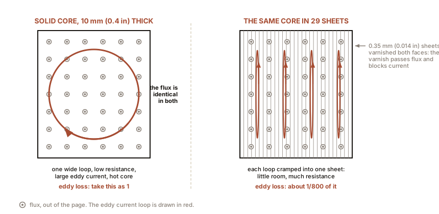
The core is iron, and iron conducts electricity. The core sits in a field that is changing sixty times a second. Rule Two applies to the core itself, exactly as it applied to the copper pipe in Chapter 4: currents circulate inside the metal, going nowhere, doing nothing but heating it.
The fix is Chapter 4’s slotted pipe, industrialised. Build the core from a stack of thin sheets, each one varnished on both faces so it is insulated from its neighbours. The magnetic field crosses the varnish without noticing, because varnish and steel are equally transparent to flux in the direction that matters. The eddy currents cannot cross it at all, so each is confined to one thin sheet, where there is little room to circulate and much resistance to fight.
The gain is dramatic, because eddy loss falls with the square of the sheet thickness. Standard power laminations are 0.35 mm (0.014 in) thick, roughly four sheets of paper. Splitting a solid 10 mm (0.4 in) core into 0.35 mm (0.014 in) laminations cuts eddy loss by a factor of about 800.
Above a few tens of kilohertz even that is not enough, and the core stops being metal at all: ferrite is a ceramic, iron oxide sintered with other oxides, magnetic like iron but electrically almost an insulator. This is why the transformer in a phone charger is a small grey ceramic lump and the transformer on the pole is a stack of steel sheets. Different frequencies, different enemies.
Hysteresis, and why the core hums
The second loss is subtler. Turning a domain around takes a small amount of work, and turning it back does not give all of it back. The iron’s magnetisation lags behind the field driving it, and the B-H curve traced through a full cycle does not retrace itself: it opens into a loop.
The area enclosed by that loop is energy lost as heat, per cycle, per unit volume of core. Sixty cycles a second, all year. It is called hysteresis loss, from the Greek for lagging behind, and it is the reason transformer steel is a specially grown alloy rather than ordinary mild steel: the alloy has a narrow loop.
The hum is the same physics being audible. The domains twitch and the core physically changes shape very slightly on each cycle, by parts in a million, a phenomenon called magnetostriction. Twice per cycle, so 120 times a second on a 60 Hz supply. That is the pitch you heard: not 60 Hz but 120 Hz, and it is why the hum of a substation is an octave-ish above the mains frequency rather than at it.
ON THE BENCH: Weigh the standby loss in your own house
Parts: a plug-in energy monitor, about $20 to $30. Cost: $20 to $30, and it usually pays for itself. Time: an evening. Hazards: none. It plugs in between wall and appliance. Method: measure the idle draw of everything with a transformer in it and nothing switched on: doorbell transformer, halogen lamp transformer, old power bricks, the microwave with its clock on, an amplifier on standby. What you should see: old iron-core adapters commonly idle at 0.5 to 3 W each. Twenty of them is 20 to 60 W, running continuously, which is 175 to 525 kWh a year. A modern switching supply idles at well under 0.1 W, and the difference between the two is almost entirely the core losses in this section. Then: unplug one adapter, wait an hour, and feel it. Cold. Plug it in with nothing attached and feel it again in ten minutes. Warm. You have now located, by hand, energy leaving the grid and entering the room for no purpose at all.
IN PLAIN ENGLISH: Iron in a coil is a bargain with two hidden charges. The bargain is that iron multiplies your magnetic field by thousands for free. The first charge is that the multiplication runs out: past a certain point the iron has given everything it has and further current buys nothing. The second charge is rent, paid every cycle whether you are using the machine or not, partly for stirring currents inside the metal and partly for dragging the iron’s own domains back and forth. Laminations cut the first rent. A good alloy cuts the second. Neither is ever cut to zero, which is why the adapter on your wall is warm.
Section 4: Maxwell’s Four Equations, With No Calculus
James Clerk Maxwell read Faraday’s drawings, took them literally, and wrote down four statements that between them describe every electrical and magnetic phenomenon in this book. Here they are in English.
One. Electric charge makes an electric field that spreads out from it. Put a charge somewhere and the space around it acquires a push on other charges, falling off with distance. Charges can exist on their own: one lonely electron is perfectly possible.
Two. Magnetic field lines never begin or end. They close into loops. This is Chapter 1’s fact about cutting magnets in half. There is no such thing as a lone magnetic pole, and every field line that leaves a north pole comes back into a south. As far as any experiment has ever been able to measure, this is exactly true.
Three. A changing magnetic field makes an electric field wrapped around it. This is Rule Two. This is Faraday’s law, and the shaking tube in Chapter 1.
Four. An electric current makes a magnetic field wrapped around it, and so does a changing electric field. The first half is Rule One, which is Ørsted’s discovery. The second half is Maxwell’s own, and he put it in because the equations did not balance without it. No experiment demanded it. Symmetry did.
That fourth statement, added for tidiness, is one of the most consequential guesses ever made.
Section 5: Therefore Light
Set statements three and four side by side and follow them round.
A changing magnetic field makes an electric field. That electric field is itself changing, because the magnetic one is. A changing electric field makes a magnetic field. Which is changing. Which makes an electric field.
The two of them can take turns, each one generating the next, and walk away across empty space with no wire and no charge and no matter of any kind involved. Maxwell’s equations even give the speed at which they must do it, from two constants that had been measured in laboratories for entirely unrelated reasons:
speed = 1 / square root of (permittivity of space x permeability of space)
      = 2.998 x 10^8 metres per second
That is the measured speed of light, to four figures. Maxwell saw it in 1865 and drew the only possible conclusion: light is an electromagnetic wave. And if light is one, then there must be others at other frequencies, waiting to be made by any circuit that can be persuaded to oscillate.
Heinrich Hertz made them in 1887 with two brass rods and a spark. Chapter 11 is what happened next.
SLOW DOWN. Check Your Understanding: Radio waves pass through your walls, your coat, and a wooden door without difficulty. Yet a phone sealed inside a biscuit tin loses all signal, and the metal mesh in a microwave oven door holds 1,000 W of microwaves inside a box you can see through. Why does thin metal stop what a brick wall does not? Answer before reading on.
Because a conductor has free electrons and brick does not. When a wave’s electric field arrives at metal, the free electrons move in response, and by moving they set up a field of their own that cancels the arriving one. The wave is reflected, and the inside of the metal box stays quiet. That is a Faraday cage, and it is named for the man who built a room-sized one at the Royal Institution in 1836, sat inside it, had a colleague charge the outside to voltages high enough to throw sparks, and reported that his instruments inside detected nothing at all.
A cage does not need to be solid, which is the part that surprises people. It needs holes small compared with the wavelength. Microwaves in an oven are 2.45 GHz, wavelength 122 mm (4.8 in), and the door mesh has holes of about 1.5 mm (0.06 in), eighty times smaller. Visible light has a wavelength of half a micrometre, thousands of times smaller than the holes, so light sails straight through and you can watch your dinner turn.
ON THE BENCH: Build a Faraday cage from a biscuit tin
Parts: a metal biscuit or paint tin with a metal lid; kitchen aluminium foil; a cheap FM radio; a mobile phone; wire mesh of two or three different hole sizes if you can find offcuts. Cost: nothing. Time: 20 minutes. Hazards: none. Do not put anything in a microwave oven. Method: tune the radio to a strong station, put it in the tin, and close the lid. Then try the phone: call it from another phone while it sits in the tin with the lid on, then with the lid off, then wrapped loosely in one layer of foil, then in two layers pressed tight. What you should see: with the lid fully on, the radio goes silent and the call fails to connect. With the lid ajar it comes back, because a gap comparable to the wavelength is a doorway. One loose layer of foil often fails and two tight layers usually succeed, and the difference is contact between the folds: a cage with a seam that does not conduct is not a closed cage. Then try mesh. Fine mesh blocks the FM band, 88 to 108 MHz, wavelength around 3 m (10 ft), easily. Chicken wire with 25 mm (1 in) holes blocks it too. Now think about which frequency each mesh would fail at, and you have designed a screened room. Where you have already relied on this: your car in a thunderstorm, the braid around every coaxial cable in your house, the metal case of a computer, and the shielded bags that circuit boards ship in.
The next three chapters spend all of this. Chapter 6 builds a motor out of Rule One and a mechanical switch. Chapter 7 gets rid of the switch. Chapter 8 gets rid of the wires to the moving part altogether.

Bench Degree
Get the degree without the diploma.
Learn the material, not how to pass the exam.