Bench Degree·ELECTROMAGNETISMchapter
Chapter 10: The Tesla Coil, a Resonant RF Machine
A neon sign transformer makes 15,000 volts. Wound into the right shape and struck at the right rhythm, it makes half a million. Nothing was added but timing.
Push a child on a swing. Push at random moments and you get nowhere: half your pushes fight the swing. Push once per swing, at the same point every time, and a hand’s worth of force builds an arc that would take both arms to produce in one shove.
That is resonance, and it is the only new idea in this chapter. Everything else is Chapters 3, 4 and 5 arranged to exploit it.
Do the electrical version before reading further, because it takes twenty minutes and it makes the rest obvious.
ON THE BENCH: Find a resonance and measure its sharpness
Parts: an air-core coil of 50 to 100 turns of 26 AWG wire on a form about 50 mm (2 in) across; capacitors of 10 nF, 22 nF and 47 nF, polypropylene or ceramic, under $4 the set; a 1 kilohm resistor; a signal generator and an oscilloscope, or one of the combined USB units at about $50, or a DSO138 kit scope at $25 plus a $30 generator. Cost: $30 to $55 if you own nothing. Time: 45 minutes. Hazards: none. Everything here is a few volts. Method: wire the generator through the 1 kilohm resistor into the coil and capacitor in series, and watch the voltage across the capacitor on the scope. Sweep the frequency slowly. What you should see: almost nothing over most of the range, then a sharp peak at one frequency, then almost nothing again. The voltage across the capacitor at the peak is several times the voltage the generator is producing. That is not a mistake and no energy has been created: the coil and capacitor are handing the same energy back and forth, and the generator only has to make up the losses. Then compute it. The formula is
f = 1 / (2 x pi x square root of (L x C)). With 200 microhenries and 47 nF it predicts 51.8 kHz. Your measurement should land within five percent, and the error will mostly be the capacitor’s tolerance. Then measure the sharpness. Find the two frequencies either side of the peak where the voltage has fallen to 71 percent of maximum. Divide the peak frequency by the gap between them. That number is Q, and for a decently wound air coil it will be somewhere between 30 and 100. Then slide a ferrite rod into the coil and watch the peak walk down the screen in real time as the inductance rises. This is how a radio tunes, and it is how a Tesla coil is tuned.
Section 1: Energy Sloshing Between Two Buckets
A capacitor stores energy in an electric field between its plates. An inductor stores energy in a magnetic field around its turns.
energy in a capacitor = half x C x V²
energy in an inductor = half x L x I²
Wire the two together and the energy cannot sit still. Start with the capacitor charged and no current flowing: all the energy is electric. The capacitor discharges through the coil, current rises, and the coil’s magnetic field builds. A quarter cycle later the capacitor is empty and the current is at maximum: all the energy has moved into the magnetic field. The collapsing field then drives current onward, charging the capacitor the other way round, and a quarter cycle later everything is electric again with the sign reversed.
It is a pendulum made of electricity. Capacitance is the spring, inductance is the mass, and the frequency is set by the two of them together and by nothing else.
Q, the quality factor, is how many swings it takes to die away. Q counts the ratio of energy stored to energy lost per radian of oscillation. A Q of 100 means it loses about one percent per radian, so it rings for hundreds of cycles. It also means the resonance is narrow: only signals within about one hundredth of the resonant frequency can excite it appreciably.
IN PLAIN ENGLISH: A high-Q circuit is a good bell. Strike it and it rings a long time on one clear note, and it ignores every note but its own. A low-Q circuit is a thud. Everything a Tesla coil does comes from being a very good bell, and everything a radio receiver does comes from the same property, which is why the next chapter is short.
Section 2: The Six Parts, in Order
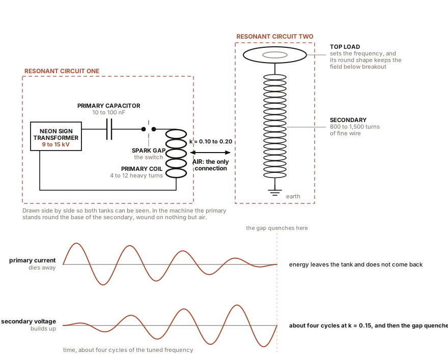
A classic spark-gap Tesla coil is two resonant circuits tuned to the same frequency, coupled loosely by a shared magnetic field. Six components.
A power supply to charge the capacitor. A neon sign transformer at 9 to 15 kV and 30 to 60 mA is the traditional choice, because it is inherently current-limited and therefore survives amateurs.
A primary capacitor, typically 10 to 100 nF, built from polypropylene film. It stores the energy for each bang. Electrolytic capacitors fail immediately and spectacularly in this service.
A spark gap, which is the switch. When the capacitor’s voltage exceeds the gap’s breakdown, the air ionises and the gap’s resistance collapses from megohms to a fraction of an ohm in nanoseconds. There is no solid-state switch of the 1890s that could do this, and it is the reason the machine was built this way.
A primary coil, four to twelve turns of heavy copper tubing or thick wire, wound as a flat spiral 200 to 750 mm (8 to 30 in) across. It is heavy because the peak current through it at resonance runs to hundreds or thousands of amperes even in a modest coil. It has a movable tap, because the tap is the tuning control.
A secondary coil, 800 to 1,500 turns of fine wire on a plastic tube, standing inside the primary but not wound on it, separated by air.
A top load, a metal toroid on top of the secondary. It looks decorative and it is not. It provides the capacitance that, with the secondary’s inductance, sets the secondary’s resonant frequency, and its rounded shape keeps the electric field at its surface below the threshold for premature breakout.
Section 3: Where the Voltage Comes From, Which Is Not the Turns Ratio
A Tesla coil with 8 primary turns and 1,000 secondary turns has a turns ratio of 125. Fed with 15,000 volts, transformer arithmetic from Chapter 3 predicts under two million volts, and a real coil of that size produces perhaps 400,000. So the turns ratio is not what is happening, and using it will mislead you in both directions.
The right calculation is energy. Whatever the primary capacitor stored has to end up in the top load’s capacitance, and it is far smaller.
half x C1 x V1²  =  half x C2 x V2²

so     V2 = V1 x square root of (C1 / C2)
Put in real numbers. A 15 kV neon sign transformer charging a 10 nF primary capacitor, discharging into a top load whose capacitance is 10 pF:
V2 = 15,000 x square root of (10,000 pF / 10 pF) = 15,000 x 31.6 = 474,000 voltsNearly half a million volts, from a sign transformer, and the mechanism is that the energy was moved from a large capacitance into a small one. The same energy in a smaller container means a higher voltage, exactly as the same water in a narrower tube stands higher.
Two things then knock it down a little. Coupling is not perfect, and 80 to 90 percent of the primary’s energy actually reaches the secondary in a well-built machine, costing about eight percent of the voltage. And the spark gap has to stop conducting, or quench, at the moment the primary current first passes through zero, because at that instant all the energy is in the secondary and any later conduction lets some of it come back. A rotary gap, a disc with electrode pins sweeping past fixed electrodes, quenches better than a fixed gap and this is most of why serious builders use one.
Coupling is deliberately kept loose, with a coupling coefficient of 0.10 to 0.20, which is the opposite of what Chapter 3 wanted. Tight coupling in a resonant pair transfers the energy in one cycle and then takes it back in the next. Loose coupling takes roughly 1/(2k) cycles to transfer, about three cycles at k = 0.15, and by then the gap has quenched and the energy is trapped where you wanted it.
| Secondary diameter | Turns | Typical peak voltage | Streamer length |
|---|---|---|---|
| 75 mm (3 in) | 900 | 100 to 200 kV | 150 to 300 mm (6 to 12 in) |
| 150 mm (6 in) | 1,200 | 300 to 500 kV | 600 to 900 mm (24 to 36 in) |
| 300 mm (12 in) | 1,500 | 1 to 2 MV | 1.8 to 3 m (6 to 10 ft) |
A warning about that last column. Streamer length is a poor voltmeter. Air breaks down at about 3 kV per millimetre (76 kV per inch) in a uniform field, but a streamer is not a uniform field, and a rule of thumb like “30 kV per inch of spark” is an estimate with a factor of two in it. Where a book quotes a coil voltage, ask whether anybody measured it or whether somebody measured a spark and multiplied.
Section 4: What a Streamer Actually Is
The purple-white tendrils are a plasma: a channel of air with its electrons stripped off, conducting, and glowing.
They start from a single free electron. There is always one available, because cosmic rays make about one ion pair per cubic centimetre per second at sea level. That electron is accelerated by the field near the top load. If the field is strong enough, the electron gains enough energy between collisions to knock an electron off the next molecule it hits, and now there are two, which make four, which make eight. That cascade is an electron avalanche.
Once the avalanche has built a short conducting channel, the tip of that channel behaves like an extension of the electrode, so the field just beyond the tip is intensified, and the process runs onward from there. Streamer tips advance at 100,000 to 1,000,000 metres per second (224,000 to 2,240,000 mph), which is far faster than any electron in them is travelling, because what propagates is the wave of ionisation and not the charge carriers.
They branch because ionisation is a threshold process and air is not perfectly uniform. Several tips compete, and whichever one gets ahead intensifies its own field and starves its neighbours, which is why the pattern looks like a river delta or a crack in glass.
The colour is emission from excited nitrogen, chiefly a band system peaking at 337 nm in the ultraviolet with a spread of bands in the violet and blue, plus a weak red line from atomic oxygen. The blue-white you see is the visible skirt of an emission that is mostly ultraviolet, which is a real hazard to eyes and skin over long exposure and is not obvious from looking.
The crackle is thunder in miniature. Each discharge heats a thin column of air to several thousand kelvin in microseconds, the column expands violently, and the pressure wave reaches your ear. Repeat it 60 to 500 times a second and the individual claps merge into a hiss.
Section 5: Building One, and Not Getting Hurt
ON THE BENCH: A small solid-state coil
Parts: a ZVS driver module with its MOSFETs, $8 to $15 online; a secondary of 800 to 1,000 turns of 28 AWG magnet wire on a 60 to 75 mm (2.5 to 3 in) plastic pipe, about $12 of wire; a primary of 4 to 6 turns of 16 AWG stranded wire; a top load bent from 40 mm (1.5 in) aluminium flexible duct into a ring 100 mm (4 in) across; polyurethane varnish; a 12 V DC supply capable of 5 A; a fluorescent tube. Cost: about $45 including a supply, less with salvage. Time: a weekend, mostly winding and waiting for varnish. Hazards, and these are real: the secondary makes 50 to 100 kV. Do not touch the top load or the streamers. A streamer contact is a radio-frequency burn, which is a surface injury rather than a deep one but is still a second or third degree burn at the point of contact. At this power level it will not stop your heart, and larger coils will. The coil also radiates broadband radio interference: keep it several metres from anything with a microprocessor in it, and away from anybody with a pacemaker or a hearing aid. Run it for under a minute at a time until you know how hot the MOSFETs get. Method: wind the secondary in a single even layer, spinning the pipe in a drill held in a vice and guiding the wire by hand. 28 AWG breaks if you pull it, so use a few ounces of tension and no more. Varnish, cure for a day. Ground the bottom of the secondary to a cold water pipe. Put the primary loosely around the bottom 15 percent of the secondary with an air gap, and connect it to the ZVS output. What you should see: streamers of 50 to 125 mm (2 to 5 in) from the top load. A fluorescent tube held 150 to 200 mm (6 to 8 in) away lights along its whole length with nothing touching it. If you get no streamers: the primary and secondary are not tuned to each other. Slide the primary up or down relative to the secondary, and change the number of primary turns in circuit, which is the only tuning control you have. Why the fluorescent tube lights without contact: mercury vapour ionises at a lower field than air does, 10.4 electron volts against 15.6 for nitrogen. The field around the top load extends for metres in every direction whether or not a streamer is visible, and the tube is a detector for it. Use it as one: walk it around the coil and map the field with your hands, which is the most Faraday-like thing in this book.
Section 6: What He Was Actually Doing With It
Tesla did not build the resonant transformer as a show. He built it because he needed a source of high-frequency, high-voltage current and none existed, and in 1891 there was no vacuum tube, no transistor, and no rotating machine that could reach 100 kHz.
The spark-gap Tesla coil was the first practical radio-frequency generator. His first patent on it, US 454,622, “System of Electric Lighting,” was filed in April 1891, and his 1891 lecture to the American Institute of Electrical Engineers introduced it to the profession. He used it to light gas-filled tubes without wires, to run early X-ray tubes, and above all as the transmitter for the tuned-circuit wireless work of Chapter 11.
It was never presented as a source of energy. It consumes electricity and turns it into radio-frequency electricity at a rather poor efficiency, and every one of Tesla’s own descriptions treats the wall supply as the input. The modern folklore that treats a Tesla coil as an energy generator has no support in any document he wrote, which is Chapter 14’s whole business.
SLOW DOWN. Check Your Understanding: Tesla demonstrated publicly by passing the output of one of his coils through his own body to light a lamp held in his hand, and used the demonstration to argue that high-frequency current is harmless. He was partly right and dangerously wrong. Where is each part? Answer before reading on.
The right part is the skin effect from Chapter 2. At 200 kHz the skin depth in a conductor is a fraction of a millimetre, and tissue is a conductor, so the current runs in the outer layer of the skin rather than through the chest. It therefore does not excite nerve and muscle the way 60 Hz does, and it will not readily stop a heart. That is a genuine physical difference and it is why the sensation is a burn rather than a paralysing shock.
The wrong part is what “harmless” is doing in that sentence. Surface current at the amperage a large coil delivers produces deep burns at the contact point, because all that power is dissipated in a small volume of skin. At kilowatt scale the current at the terminal reaches tens of amperes peak, which is enough to disrupt cardiac rhythm even at radio frequency. And the hazard people actually die from is upstream: the primary circuit sits at 9 to 15 kV at 60 Hz with over a joule stored in the capacitor, which is straightforwardly lethal, and the capacitor stays charged after the power is switched off. Discharge it with a grounded shorting stick every single time before your hands go near it. Tesla’s demonstration was true about the secondary and silent about the primary, and the primary is the part that kills builders.
Next: the same tuned circuit, used to receive rather than to transmit, and a patent fight that was decided by the Supreme Court five months after the claimant died.

Bench Degree
Get the degree without the diploma.
Learn the material, not how to pass the exam.