Bench Degree·ELECTROMAGNETISMchapter

Chapter 3: The Transformer, and the Real Reason AC Won
Two coils that never touch, sharing one lump of iron. It has no moving parts, it cannot be made to work on direct current at all, and it decided the shape of every electrical grid on earth.
Chapter 2 left 125 watts warming an extension cord on your floor. That is eight percent of a kettle, thrown away as heat in copper, over 30 m (100 ft).
Now do the arithmetic that fixes it.
The loss in a wire is P = I² x R. The resistance is
fixed by the copper: 0.8 ohms in that cord’s round trip, and the only
way to lower it is more metal. But the current is not fixed. Current is
power divided by voltage. Deliver the same 1,500 W at 1,200 volts
instead of 120 and the current falls from 12.5 A to 1.25 A.
loss at 120 V   = 12.5² x 0.8 = 125 W
loss at 1,200 V = 1.25² x 0.8 = 1.25 W
A tenfold rise in voltage cut the loss by a factor of one hundred, in the same wire, delivering the same power. The loss falls as the square of the voltage rise, because the current falls in proportion and the loss depends on current squared.
That is the whole economic argument of nineteenth-century electrification, and it is worth nothing at all unless you can actually change the voltage. So build the machine that does.
Section 1: Two Coils and One Piece of Iron
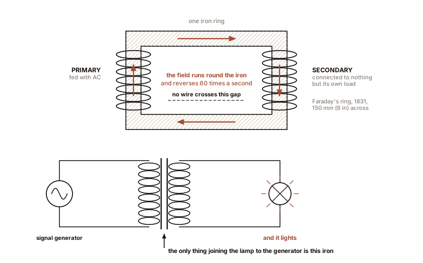
Wind a coil on an iron ring. Wind a second, separate coil on the other side of the same ring. The two coils do not touch, and there is no electrical path between them.
Feed alternating current into the first coil, the primary. By Rule One, current makes a magnetic field, and the iron ring gathers that field and carries it around to the other side. Because the current alternates, the field alternates with it.
Now the second coil, the secondary, is sitting in a magnetic field that is changing sixty times a second. By Rule Two, a changing field drives current in a coil. Voltage appears at the secondary’s terminals.
Nothing crossed between the two coils except a magnetic field in a piece of iron. That is a transformer. Faraday built the first one in 1831, on an iron ring 150 mm (6 in) across wound with two separate coils, and he built it as a demonstration of Rule Two rather than as a machine for anybody to use.
ON THE BENCH: Wind a transformer and prove the turns ratio
Parts: a ferrite toroid or E-core, free from any dead computer power supply or salvaged from a scrap wall adapter; 15 m (50 ft) of 26 to 30 AWG magnet wire, about $8; a doorbell or thermostat transformer with a 16 V AC output, about $14; a multimeter; sandpaper. Cost: about $22, less if you salvage. Time: an hour, most of it winding. Hazards: the doorbell transformer’s input side is line voltage and stays in its box. Everything you touch is on the 16 V side. Method: wind 100 turns on one half of the core and count them out loud. Wind 50 turns on the other half. Scrape all four ends bare. Feed the 16 V AC into the 100-turn winding. Measure AC volts across the 50-turn winding. What you should see: about 8 volts, half the input, because you have half the turns. Rewind the secondary to 200 turns and you will read about 32 volts. Rewind it to 25 and you will read about 4. Then, the important test: switch the supply to a 9 V battery instead. The output is zero, except for one brief flick of the needle at the instant you make the connection and another when you break it. Steady current makes a steady field, a steady field is not a changing field, and Rule Two gives you nothing. This is the single most consequential null result in the history of electrical engineering, and it takes four seconds to reproduce. If your numbers are off by more than ten percent: you miscounted turns, which everyone does, or the two windings are not sharing the core well. On a toroid, spread each winding around a full half of the ring.
Section 2: The Turns Ratio Is the Whole Design
The relationship you just measured is exact, and it is the simplest in this book after Ohm’s law.
V_secondary / V_primary = N_secondary / N_primaryVoltages are in the same ratio as turn counts. Twice the turns, twice the volts. A hundredth of the turns, a hundredth of the volts. The reason is Chapter 1’s Section 7: every single turn of wire feels the same changing field and contributes its own share of push, so the pushes add up turn by turn.
More turns on the output than the input is a step-up transformer. Fewer is a step-down. The same physical object runs either way; which is which depends only on which winding you feed.
IN PLAIN ENGLISH: A transformer is a lever for electricity. A lever trades distance for force and gives you back exactly what you put in, minus friction. A transformer trades voltage for current and gives you back exactly what you put in, minus heat. You cannot get more out than you put in, and nobody has ever managed it.
Section 3: Power Is Conserved, So the Current Goes the Other Way
If a transformer raises voltage, something has to give, and it is current.
V_primary x I_primary = V_secondary x I_secondary (ignoring losses)Push 120 V at 10 A into a 1:10 step-up transformer and you are supplying 1,200 W. Out comes 1,200 V, and since the power cannot grow, the current out is 1,200 W divided by 1,200 V, which is 1 A.
Voltage up ten times, current down ten times, power unchanged. Every step-up transformer is simultaneously a step-down transformer for current, and that second fact is the one that mattered commercially, because it is current that heats wires.
Real transformers lose a little. A good large one runs at 98 to 99.5 percent efficiency; a phone charger’s tiny one is nearer 90 percent, and the warmth in your hand is the difference. Where those losses come from, and how the design fights them, is Chapter 5.
SLOW DOWN. Check Your Understanding: A transformer has 500 turns on the primary and 50 on the secondary. You feed 240 V AC into the primary. What comes out, and can you power a 1,000 W load from it? Work it out first.
The turns ratio is 50/500, so the output is 24 volts. Now the second half, which is where people go wrong. The turns ratio tells you nothing about how much power the transformer can pass. A 1,000 W load at 24 V draws about 42 A, and that current has to flow in the secondary winding. If you wound that secondary from thin wire, it will get hot, the enamel will fail, and the transformer will burn out with a perfectly correct turns ratio right up to the moment it dies. Voltage is set by turns. Power is set by the copper cross-section and the size of the core. Which is exactly what the two numbers on a transformer nameplate tell you, and why there are two of them.
Section 4: The Arithmetic That Killed the DC Grid
Now take the extension cord calculation and run it to the scale of a city.
Suppose you must deliver 10,000 W to a customer 5,280 ft (1.6 km) away, which is one mile, and you are willing to lose 5 percent of it, 500 W, in the wires. Copper’s resistivity is 1.72 x 10 to the minus 8 ohm metres, and out-and-back the conductor length is 3,218 m (10,560 ft).
At 120 volts DC. The current is 10,000/120, which is
83.3 A. To lose only 500 W at that current the line resistance must be
under 500/83.3², which is 0.072 ohms. Working back through
R = ρL/A, the conductor cross-section must be 769 mm². That
is seven times the cross-section of 4/0 AWG cable, the heaviest thing an
electrician normally handles. At copper’s density of 8,960 kg/m³, the
copper in that mile of line weighs 22,175 kg.
At 12,000 volts AC, stepped up at the generator and back down at the customer. The current is 10,000/12,000, which is 0.83 A. The allowed line resistance is now 720 ohms, and the required cross-section is 0.0769 mm², which is thinner than a human hair. The copper needed is 2.2 kg.
Read those two numbers side by side.
| Copper for one mile (1.6 km) of line | |
|---|---|
| 120 V DC | 22,175 kg (48,890 lb, 24 US tons) |
| 12,000 V AC, electrically required | 2.2 kg (4.9 lb) |
| 12,000 V AC, at the practical minimum wire size | 60 kg (132 lb) |
The pure ratio is 10,000 to 1, and it is exactly the square of the hundredfold voltage step. In practice you cannot string a hair between poles, so the thin line is built at 14 AWG or heavier for mechanical reasons, and the honest ratio is about 370 to 1.
Either way, and this is the point, the difference is not a percentage. It is between a wire and a wall of metal. Thomas Hughes, working from contemporary records, computed roughly a hundredfold copper saving for a comparable task under the assumptions of the 1880s. The exact figure depends on what you hold constant. The direction and the order of magnitude have never been in doubt by anyone who did the arithmetic, including Edison.
Section 5: Edison’s Actual Problem
The story usually told is that Edison was stubborn about direct current. The story is unfair, and the truth is more useful.
Edison’s Pearl Street station opened in lower Manhattan on 4 September 1882, serving 59 customers and 400 lamps at 110 V DC over a radius of about 800 m (2,600 ft, half a mile). By January 1883 it was serving 508 customers and 10,164 lamps. It was not a generator; it was a complete system, with meters that measured what people used and a billing department that charged them for it. It worked.
What it could not do was reach. That 800 m (2,600 ft, half a mile) radius was not a policy. It was the distance at which 110 V DC ran out of usable voltage in the copper Edison could afford to bury. To light the next square mile you needed another complete generating station, not a branch line. By 1890 Manhattan had 121 separate DC generating stations.
And here is the fact that settles it. There is no such thing as a DC transformer. You proved that yourself four sections ago with a 9 V battery, and the reason is Rule Two: a transformer runs on a changing field, and steady direct current does not change. Edison had no lever. He could not generate at high voltage and deliver at low, because he had no way to get from one to the other. He was defending a system that was excellent inside a radius set by physics he could not move.
The century since has not repealed this. It has gone around it. Long-distance high-voltage DC links exist today and are superb for specific jobs: the Pacific Intertie runs 1,362 km (846 miles) from Oregon to Los Angeles at plus and minus 500 kV DC, carrying 3,100 MW. But it changes voltage by rectifying AC at one end and inverting back to AC at the other, using power electronics that did not exist until the 1950s. Even modern DC transmission needs an AC transformer at each end to make its voltage.
Section 6: The Ladder from the Turbine to Your Table Lamp
Here is the full chain, with the real voltages, and every step between them is a transformer.
| Stage | Where | Voltage | Direction |
|---|---|---|---|
| Generation | the powerhouse | 13.8 kV | |
| Transmission | plant step-up substation | 115 to 765 kV | up, 10 to 55 times |
| Sub-transmission | regional substation | 69 to 115 kV | down |
| Distribution | local substation | 12.47 kV | down |
| Service | the can on the pole | 120/240 V | down, about 100 times |
Five transformers between the turbine and your lamp, and the whole
ladder exists for one reason: carry it high, use it
low. The tall lattice towers are high because copper is
expensive and I²R is unforgiving. The grey canister on the
pole outside is low because 120 volts will not kill you across a dry
hand and 12,470 will kill you across a room.
ON THE BENCH: Read a real transformer nameplate
Parts: your eyes, and either a pole transformer within sight or the plate on any piece of powered equipment: a microwave oven, a doorbell transformer, a laptop brick, a welder. Cost: nothing. Time: 20 minutes. Hazards: none if you read from the ground. Do not climb anything and do not open anything. Method: find four numbers. Primary voltage. Secondary voltage. The kVA rating. The frequency. What you should see, and what each one means: the two voltages give you the turns ratio directly, without opening the case. The kVA rating is the power the copper and core can carry continuously without cooking, and it is a completely separate fact from the voltage ratio. The frequency is not decoration: a 60 Hz transformer run at 50 Hz sees more flux per cycle in its core and can saturate and overheat, which is Chapter 5 and is why equipment shipped between continents needs checking. A typical residential pole transformer in North America reads 12,470 V primary, 120/240 V secondary, 25 or 50 kVA. At 25 kVA and 240 V it can supply about 104 A, which is roughly two average houses on a hot afternoon. Then answer the question in Chapter 1’s promise list: what will this transformer not do? It will not change frequency, it will not work on DC, it will not deliver more than its kVA without overheating, and it will not step 12,470 down to anything except 120/240, because the turns are already wound.
Everything so far has treated the magnetic field as a thing that simply appears when you ask for it. That will not survive Chapter 5, where a real core saturates, wastes energy, and heats up. So the next chapter goes back to the field itself and looks at it properly, with iron filings, a compass, and a copper pipe that makes a magnet fall as though through honey.

Bench Degree
Get the degree without the diploma.
Learn the material, not how to pass the exam.