Bench Degree·ELECTROMAGNETISMchapter

Chapter 12: Wireless Power, What Wardenclyffe Was For
A charging pad on your desk moves fifteen watts across an air gap at eighty percent efficiency. A tower on Long Island was meant to move megawatts across an ocean. The difference between those two sentences is a number, and the number is in this chapter.
Put a phone on a wireless charging pad. Now slide a sheet of paper under the phone. It still charges. Slide in a paperback book, 20 mm (0.8 in) thick, and it stops.
That is the whole engineering problem of wireless power in one gesture, and it costs nothing to perform. The distance over which magnetic coupling works is set by the size of the coils, and the coils in a phone are about 40 mm (1.6 in) across.
So the honest question about Wardenclyffe is not whether Tesla was sincere or brilliant. He was both. The question is what he thought would carry power from Shoreham, Long Island, to everywhere else on earth, and whether the numbers support it.
ON THE BENCH: Measure a wireless charger honestly
Parts: a Qi charging pad, $12 to $20; a USB power meter that reads volts, amps and watt-hours, $12; a phone; a stack of cards, paper and thin plastic to make measured gaps; a plastic ruler. Cost: about $30. Time: an hour. Hazards: none. Keep metal off the pad: a coin left on a charger heats up by the eddy currents of Chapter 4, and that is the mechanism, not a fault. Method: put the meter between the wall adapter and the charging pad, so you are reading what goes in. Charge the phone from 30 to 40 percent and record the watt-hours consumed. Then repeat with a 3 mm (0.12 in) shim under the phone, then 6 mm (0.24 in), then 10 mm (0.4 in), and find the gap at which charging stops. What you should see: on a modern pad, 70 to 85 percent of the energy from the wall reaches the battery when the phone is flat on the pad. By 8 to 12 mm (0.3 to 0.5 in) it is failing, and above that it stops entirely rather than degrading gracefully, because the protocol gives up rather than waste power. Then feel the pad after ten minutes. Warm. That warmth is the fifteen to thirty percent, and it is core loss and copper loss from Chapter 5 plus the electronics. The number to carry forward: a coil 40 mm (1.6 in) across works across about 8 mm (0.3 in), which is a fifth of its own diameter. Hold on to that ratio.
Section 1: What Was Actually Built
Wardenclyffe was real, it was large, and it is documented.
Construction began in 1901 at Shoreham on the north shore of Long Island, on a site Tesla chose for its deep water table and its proximity to the transatlantic shipping lanes. The tower stood 57 m (187 ft) tall, a skeletal wooden frame of the same construction as a grain elevator. On top sat a copper-clad hollow electrode, mushroom-shaped, 21 m (68 ft) across. The shape was not decorative: a broad rounded top load maximises capacitance to ground while keeping the surface electric field below the breakdown threshold, which is Chapter 10’s toroid at forty times the size.
Below ground it was at least as ambitious. A shaft went straight down 37 m (120 ft), and from its base iron pipes were driven outward and downward into the water table. Tesla described this underground structure as the most important part of the installation, and in his conception it was one plate of an enormous capacitor whose other plate was the conducting upper atmosphere, with the air between them as the dielectric.
The laboratory building at the base was designed by Stanford White, the leading American architect of the day. That detail tells you what Tesla thought he was building. You do not hire the architect of Madison Square Garden for a test rig.
J. P. Morgan put in $150,000 in 1901, roughly $5 million in today’s money. Morgan was not a philanthropist and he was the most powerful banker in America; his interest was the commercial prospect of wireless communication in competition with Marconi.
And that is where the trouble was, because it is not what Tesla was building. His notebooks and his June 1900 Century Magazine article are explicit that the goal was global wireless power distribution, with communication as a minor secondary use. When Morgan understood that the proposed system would radiate power that any receiver anywhere could tap, with no meter and no way to bill it, he declined further investment. There was no revenue model. He wrote to Tesla in 1903 to say so.
The property was sold in 1915 and the tower demolished in 1917. The scrap brought $1,750. The base building survives and is now the Tesla Science Center at Wardenclyffe.
Section 2: Two Readings, and He May Not Have Separated Them
There are two physically distinct ways to send power without wires, and the whole assessment of Wardenclyffe turns on which one Tesla meant.
Radiation
Broadcast a wave from an antenna. This is Chapter 11, and it works beautifully for signals. Power spreads over an expanding sphere, so the intensity at distance r is the transmitted power divided by 4 pi r squared. Double the distance, quarter the intensity. A receiving antenna captures whatever fraction of that sphere it happens to intercept, which for any practical antenna at any useful distance is a vanishing fraction.
Tesla rejected this mechanism explicitly, repeatedly, and in print. When critics said he was merely broadcasting radio waves, he objected in technical detail. That rejection is on the record and it is consistent with his understanding of the physics, which matters because the accusation is still made.
The Earth as a resonant cavity
His stated mechanism was different in kind. The earth is a conductor. Above about 60 km (37 miles) the atmosphere is ionised by sunlight into a conducting plasma. Between them lies a shell of imperfectly insulating air about 80 km (50 miles) thick.
That geometry is a resonant cavity, in exactly the sense that a room is a resonant cavity for sound. Waves launched upward reflect down from the ionosphere, reflect up from the ground, and go round. At certain frequencies the reflections reinforce, standing waves form, and the system stores energy instead of dissipating it by spreading out. Energy fed into a resonance does not obey the inverse-square law, because it is not going anywhere.
The fundamental frequency of that cavity is set by the time a wave takes to travel round the earth. The mean circumference is 40,075 km (24,901 miles), light covers it in 0.1336 seconds, and the reciprocal is 7.49 Hz.
That is the Schumann resonance, and it is entirely real. Winfried Schumann calculated it in 1952. Balser and Wagner measured it in 1960 and found peaks at 7.83, 14.3, 20.8, 27.3 and 33.8 Hz. It is maintained continuously by lightning: about 100 strokes somewhere on earth every second, each injecting a broadband pulse into the cavity, which responds at its own frequencies the way a bell responds to being hit.
Tesla was working experimentally on this geometry in 1899, fifty-three years before anyone calculated it, and his notebooks contain estimates of an earth resonance in the range of a few hertz to a few tens of hertz. That is a remarkable piece of intuition and it should be said plainly.
Section 3: Why It Could Not Have Worked Anyway
Three obstacles, and none of them is a matter of scale or funding.
Antenna size. A wave at 7.83 Hz has a wavelength of 38,000 km (23,600 miles), almost the circumference of the planet. An efficient radiator must be an appreciable fraction of a wavelength. The US Navy’s Project ELF transmitter at Clam Lake, Wisconsin, built specifically for this band and operating from 1989 to 2004, used a ground antenna with 45 km (28 miles) of conductor, drew megawatts, radiated a few tens of watts of extremely low frequency, and communicated with submerged submarines at a few characters per minute. A tower 57 m (187 ft) tall cannot couple efficiently to a 38,000 km (23,600 mile) wave. It is not close.
The frequency he actually used. Tesla’s magnifying transmitter at Colorado Springs resonated at roughly 150 kHz, and the Wardenclyffe design was in the same region. At 150 kHz the earth and ionosphere do not behave as a resonant cavity at all; they behave as a lossy transmission line, with ground-wave attenuation of roughly 2 dB per thousand kilometres over average ground. Power delivered to the far side of the earth would be measurable and useless. His theoretical framework was at a few hertz and his hardware was at 150 kilohertz, and those are not the same machine.
Extraction at the receiving end. Even granting global distribution, getting power back out of an extremely low frequency field requires a receiving antenna, and at those wavelengths a practical receiver extracts almost nothing. The Navy’s receiving submarines trailed loops hundreds of metres long to collect enough for one bit a minute.
IN PLAIN ENGLISH: He identified a real resonance of the whole planet before anyone had measured it, which is a genuine and undercredited insight. He then proposed to drive it with a tower a millionth of a wavelength tall, at a frequency twenty thousand times too high. The concept was decades ahead. The hardware was not a scaled-down version of something that would have worked bigger; it was the wrong instrument for the note.
Section 4: The Same Principle, at the Right Scale
Where Tesla’s resonance argument is correct is at short range, and in 2007 a group at MIT quantified it precisely.
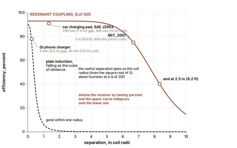
Marin Soljacic and colleagues published in Science an experiment with two self-resonant coils, each 600 mm (24 in) across, both tuned to 9.9 MHz. They put 60 W into one and got 45 W out of the other at a separation of 2 m (6.6 ft): 75 percent efficiency. At 2.5 m (8.2 ft) it fell to about 40 percent.
To see why that is remarkable, compare it with plain induction. Ordinary inductive coupling between two coils falls off roughly as the cube of the ratio of coil radius to separation. At 2 m (6.6 ft) with coils of that size, plain induction would give a coupling of a few percent at best. They got 75 percent, and the entire difference is resonance.
The mechanism is Chapter 10’s bell. Energy fed into a high-Q resonant coil is not immediately radiated; it circulates in the near field around the coil. If a second coil tuned to the same frequency is inside that near field, energy transfers into it preferentially, because it is the only thing in the vicinity that will accept energy at that note. The useful range scales not with the coil radius but with the coil radius times the square root of Q. For Q of 200, that is a factor of about fourteen. It is the difference between a transformer that works at a centimetre and a charger that works at thirty.
ON THE BENCH: Build a resonant pair and watch resonance earn its keep
Parts: two identical flat coils, about 200 mm (8 in) across, 30 to 40 turns of 24 AWG magnet wire, about $10; capacitors to resonate them near 100 kHz, typically 2.2 to 4.7 nF, and a couple of nearby values for detuning, under $4; a signal generator able to reach 100 kHz and drive a load, or a small class-D audio amplifier; a 100 ohm resistor as the receiving load; a scope or two multimeters that read AC volts at 100 kHz. Cost: $40 to $70 depending on what you own. Time: an afternoon. Hazards: low voltage throughout. The coils get warm. Method: measure each coil’s inductance, compute the capacitor that resonates it near 100 kHz with
C = 1 / ((2 pi f)² L), and fit it. Face the coils at a separation of one coil radius, 100 mm (4 in). Sweep the drive frequency and find the peak. At the peak, measure the power going in and the power arriving in the 100 ohm load. What you should see: at resonance and one radius apart, 60 to 85 percent efficiency. Then walk the coils apart in 50 mm (2 in) steps and plot efficiency against distance. It holds up better than you expect and then falls off a cliff. Then detune the receiver by swapping its capacitor for one 20 percent away. Efficiency collapses to under ten percent, and it collapses abruptly rather than gradually. That cliff is the signature of a high-Q system and it is the whole reason the technique is useful: a transmitter at one frequency powers only receivers tuned to that frequency and ignores everything else in the room.
Section 5: In Your Pocket, and Under Your Car
The Qi standard, adopted in 2008 by the Wireless Power Consortium, is resonant inductive coupling in a consumer product. It operates between 87 and 205 kHz, delivers 5 to 15 W in its common profiles and up to 50 W in extended ones, works across up to 40 mm (1.6 in) for extended-range designs and more typically 4 to 8 mm (0.16 to 0.31 in), and achieves 70 to 85 percent from the wall to the battery. The transmitter and receiver negotiate over a data channel so that the transmitter can adjust its frequency to match the receiver’s resonance, which is the detuning cliff being actively avoided. Over four billion Qi devices have shipped.
The automotive version is SAE J2954, which specifies 85 kHz, delivers 7.7 kW across a 200 mm (7.9 in) air gap at better than 90 percent efficiency, and tolerates parking misalignment of plus or minus 75 mm (3 in). The coils are about 300 mm (12 in) across. Note the ratio again: 300 mm (12 in) coils, 200 mm (7.9 in) gap. Two thirds of a coil diameter, and that is with resonance, good Q, and twenty years of engineering. The gap does not scale with the money spent; it scales with the coil.
Medical implants use the same physics at 5 to 30 mm (0.2 to 1.2 in) and milliwatts to watts, for cochlear implants and deep-brain stimulators, where the frequency is chosen to minimise heating of tissue.
Two other approaches exist and are not this principle, and are worth naming so they are not confused with it. Laser power beaming sends a collimated optical beam, which is radiation rather than resonance, and has demonstrated roughly 100 W over 100 m (330 ft) to a drone. Microwave beaming from orbit for satellite solar power is also radiation, needs a receiving antenna measured in kilometres, and remains a proposal.
Section 6: HAARP, Since It Will Come Up
Any chapter about Wardenclyffe now has to deal with HAARP, because a large body of writing connects them.
The High-frequency Active Auroral Research Program sits at Gakona, Alaska, and has been owned and run by the University of Alaska Fairbanks since 2015. It is 180 crossed-dipole antennas in a 12 by 15 array over 13 hectares (33 acres), radiating up to 3.6 MW between 2.7 and 10 MHz.
What it does: it heats small patches of the ionosphere with high-frequency radio, raising the electron temperature and density, and then measures what happens with instruments on the ground and on satellites. One well-studied capability is generating extremely low frequency waves by switching the heating on and off at a low rate, which makes the ionosphere itself into a large antenna. Those waves penetrate seawater, which is why the Navy funded it.
What it does not do: influence weather. A storm system moves energy at the terawatt scale. HAARP radiates 3.6 MW, six orders of magnitude short, into a layer that is not mechanically coupled to the lower atmosphere. The claims are not marginal, they are not close. Its ground-level power density outside the fence is below public exposure limits, which is measured and published.
The connection to Tesla is thematic. Both treat the ionosphere as an active medium rather than empty space. HAARP uses none of Tesla’s circuits, frequencies or mechanisms, and it activates nothing of his. All of its research is unclassified and published in the ordinary geophysics journals, and the facility holds public open days.
SLOW DOWN. Check Your Understanding: If resonant coupling escapes the inverse-square law, and a resonance can be extremely high-Q, why can you not simply build a very high-Q resonant pair and transmit power across a city? Answer before reading on.
Because Q buys you range in units of coil size, and nothing else does. The useful separation goes roughly as the coil radius multiplied by the square root of Q, and both terms have hard ceilings. A Q of 200 is good; a Q of 2,000 is exotic laboratory work; and the square root means that a tenfold improvement in Q buys a factor of three in distance. To reach a kilometre you would need coils measured in tens of metres, and then the resonance is so narrow that it drifts out of tune when a truck drives past.
And there is a second limit that is not about efficiency at all. Everything outside the transmitter’s near field is radiation, which is Chapter 11, and radiation obeys the inverse square law no matter how good your resonator is. The resonant advantage exists only within the near field, which extends about one wavelength divided by 2 pi from the coil. So the reach of resonant coupling is bounded by geometry from below and by radiation from above, and Wardenclyffe was trying to live in the gap between them at a scale where there is no gap.
The tower is the ambition. The next chapter is the laboratory that produced the data the tower was built on, and it is where the record gets genuinely interesting, because some of it is verified, some of it is plausible, and some of it is neither.

Bench Degree
Get the degree without the diploma.
Learn the material, not how to pass the exam.