Bench Degree·FLUID POWERchapter
Chapter 20: Aircraft and Heavy Equipment
An airliner’s flight controls are hydraulic for two reasons: force per kilogram, and the fact that a hydraulic actuator holds its position while consuming nothing at all. And a skid-steer turns on the spot because there is no mechanical connection between its two sides.
Two families of machine, both at the extreme end of what fluid power is for, and both making the same argument from opposite directions.
An airliner cares about mass above everything. A skid-steer cares about being able to do something no gearbox can. Both end up hydraulic, and for reasons you can now derive.
Section 1: Why an Airliner’s Controls Are Not Electric
An airliner’s control surfaces need to be moved with large forces, quickly, precisely, and against aerodynamic loads that change constantly. There are three candidate technologies and the aircraft industry considered all of them.
Reason one: force per kilogram, and it is not close.
Take an aileron actuator: 60 mm (2.4 in) bore at 21,000 kPa (3,045 psi).
area  =  0.7854 x 60 x 60  =  2,827 mm2   (4.38 in2)
force =  21 MPa x 2,827     =  59,400 N    (13,350 lb)
Nearly sixty kilonewtons, six tonnes-force, from an actuator weighing perhaps 8 kg (18 lb) including its manifold and its position sensor. That is about 7,400 N of force per kilogram of actuator.
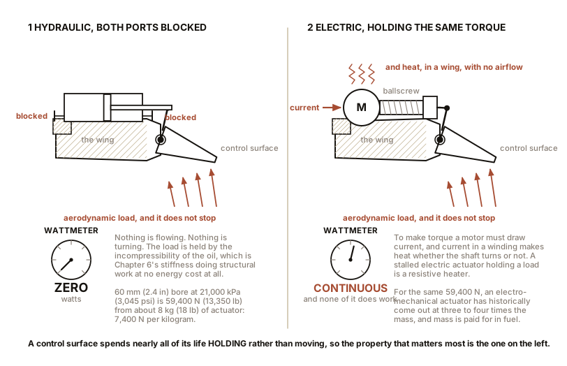
An electromechanical actuator producing 59,400 N needs an electric motor, a gearbox or a ballscrew to convert rotation to a large linear force, and a structure to react it. Historically that came out at three to four times the mass, and mass on an aircraft is paid for in fuel every hour of every flight for thirty years.
Reason two, which is the more interesting one: a hydraulic actuator holds its load for free.
Block both ports of a hydraulic cylinder holding an aerodynamic load and it holds. The pump is not working, no fluid is flowing, and nothing is being dissipated. The load is held by the incompressibility of the oil, which is Chapter 7’s stiffness doing structural work at zero energy cost.
Now hold the same load with an electric motor. To produce torque, a motor must draw current, and current in a winding produces heat whether the shaft turns or not. A stalled electric actuator holding a steady load is a resistive heater, which is Chapter 11’s point about stall, and on an aircraft that means continuous electrical load and a cooling problem inside a wing where there is neither room nor airflow.
A control surface spends almost all of its life holding a position rather than moving. So the property that matters most is the one hydraulics gets for nothing.
Reason three: stiffness, and the word for what happens without it is flutter.
A control surface on a compliant actuator is a mass on a spring in an airstream, and a mass on a spring in an airstream can extract energy from the airflow and oscillate with growing amplitude. That is flutter, and it destroys aircraft in seconds. The actuator’s stiffness is part of the aeroelastic design of the wing, and Chapter 7’s arithmetic says that only a very stiff fluid in short, hard lines delivers it. Air would be a thousand times too soft. This is the single least negotiable requirement in the list.
And the pressure is high for Chapter 8’s reason. Aircraft run at 21,000 kPa (3,045 psi) traditionally, and the A380, A350 and F-35 run at 35,000 kPa (5,075 psi). Higher pressure means smaller actuators, smaller pipes and less fluid, all of which is mass. The cost is that everything must be built to a higher standard and that Chapter 22’s injection hazard becomes more severe.
Section 2: Three Systems, and What Independence Actually Requires
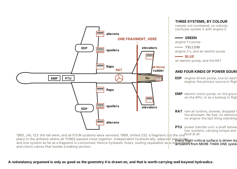
An airliner does not have a hydraulic system. It has three or four, and they are given colours rather than numbers so that nobody can confuse “system 2” with “engine 2”.
An Airbus A320 has Green, Blue and Yellow. A Boeing 747 has four, numbered. Each system has:
- Its own reservoir, pressurised by engine bleed air so the pumps are never asked to suck, which is Chapter 10 Section 4 taken seriously.
- Its own fluid, with no path between systems.
- Its own pumps, and its own set of actuators.
And every flight-critical surface is driven by actuators fed from more than one system, so losing any single system leaves every surface still controllable.
The power sources are worth naming because they are all different.
Engine-driven pumps, bolted to the accessory gearbox of each engine. Variable displacement piston pumps, and the primary source in flight.
Electric motor pumps, which can run on the ground, on the auxiliary power unit, or as a backup in flight.
A ram air turbine, the RAT: a small propeller stowed in the fuselage that drops into the airstream when everything else has failed and is driven by the aircraft’s own forward motion. On the A320 it drives the Blue system’s pump. It needs no fuel, no electrical power and no engine. It is the last thing standing.
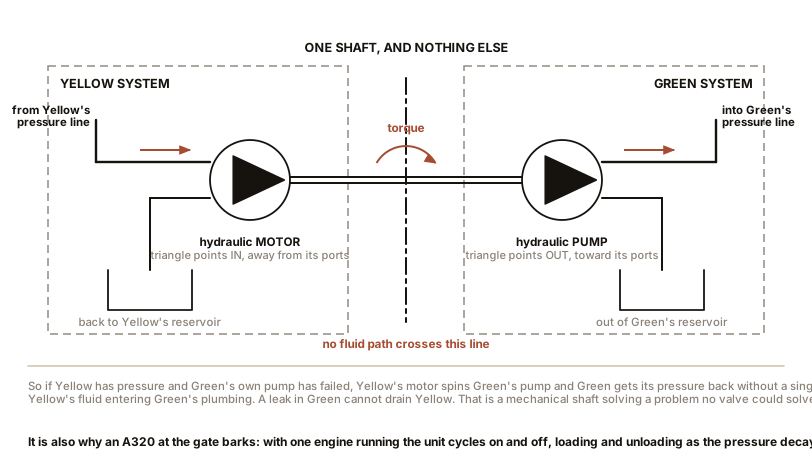
And the power transfer unit, which is the genuinely elegant one. The PTU is a hydraulic motor on one system’s pressure line, mechanically coupled by a shaft to a hydraulic pump on another system.
No fluid crosses between the two systems. Only power does. So if the Yellow system has plenty of pressure and the Green system’s pump has failed, the Yellow motor spins the Green pump and Green gets its pressure back without a single drop of Yellow’s fluid entering Green’s plumbing. A leak in Green cannot drain Yellow. That is the whole point, and it is a mechanical shaft solving a problem that no valve could solve.
It is also why an A320 sitting at a gate makes a rhythmic barking noise. With one engine running, the PTU cycles on and off as the pressure in the unpowered system decays and is restored, and the pump loading and unloading produces that sound. Passengers assume something is wrong. It is a system working exactly as designed.
And now the honest lesson, which cost lives to learn.
Independence on a schematic is not independence in space. Two accidents made this unavoidable.
In 1985, JAL Flight 123, a Boeing 747, suffered an aft pressure bulkhead failure that destroyed the vertical stabiliser. All four hydraulic systems ran through the tail and all four were severed. The aircraft flew for 32 minutes with no flight controls at all.
In 1989, United Flight 232, a DC-10, suffered an uncontained failure of the tail-mounted engine. Fragments cut through the one part of the airframe where all three hydraulic systems’ lines passed close together. The crew flew the aircraft to Sioux City using differential thrust on the two remaining engines and 185 of the 296 aboard survived.
In both cases the systems were fully independent hydraulically and physically adjacent. The consequences for design were direct and permanent: hydraulic fuses, which are valves that close automatically if the flow through them indicates a downstream rupture; physical routing separation as a design requirement rather than a convenience; and check valves that isolate a leaking section. A redundancy argument is only as good as the geometry it is drawn on, and that is worth carrying well beyond hydraulics.
A note on the fluid. Airliners use phosphate ester fluid, a water-free synthetic in the HFD family of Chapter 9, sold as Skydrol or Hyjet. It is fire resistant, which is the reason for choosing it, and it is genuinely unpleasant: it attacks most paints, many rubbers and skin, and it must never be mixed with mineral oil. Every seal, hose, coating and gasket in the aircraft is specified for it. Which is Chapter 9’s lesson again: the fluid and the materials are one decision.
And one thing that did change. The frontier now is the electro-hydrostatic actuator, which is a self-contained unit with its own small electric motor, its own pump, and its own few hundred millilitres of fluid, taking electrical power in and giving hydraulic force out at the actuator itself. The Airbus A380 and the F-35 use them, alongside conventional actuators, as a dissimilar backup. It keeps hydraulics for the muscle and abandons the aircraft-wide plumbing, which addresses the mass of the pipework rather than the mass of the actuator. Whether that architecture eventually displaces central hydraulics is a live question and not a settled one.
Section 3: The Hydrostatic Transmission
Now the ground machinery, and the idea that makes it possible.
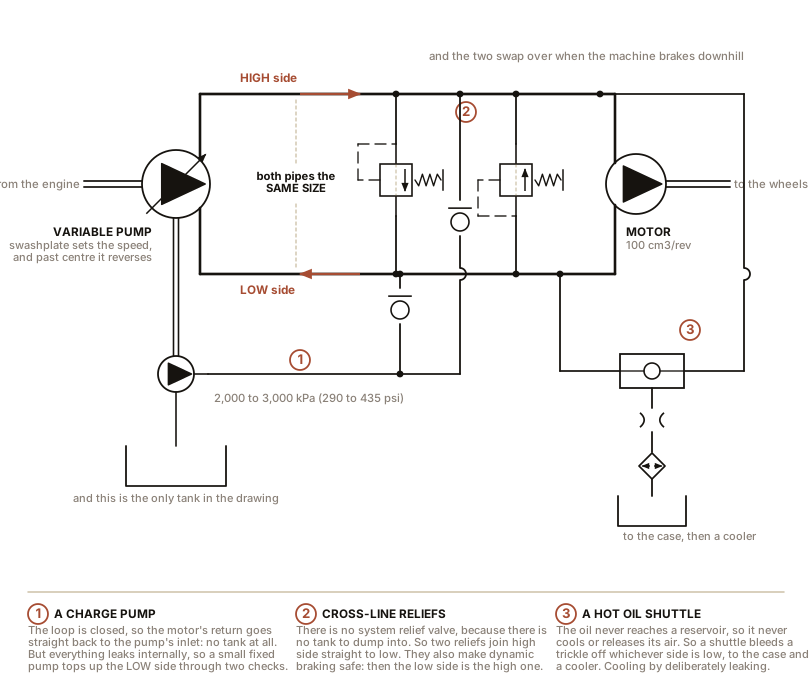
Put a variable displacement pump and a hydraulic motor in a closed loop and you have a gearbox with no gears.
The arithmetic is Chapter 11’s motor equations. At 35,000 kPa (5,075 psi), take a variable pump of up to 50 cm³ per revolution (3.05 in³) driven at 2,200 rpm, feeding a fixed motor of 100 cm³ per revolution, or 6.10 in³, at a flow of 110 litres/min (29 gal/min):
at full pump displacement:
flow   =  50 x 2,200 / 1,000  =  110 litres/min   (29 gal/min)
motor speed  =  110 x 1,000 / 100  =  1,100 rpm
motor torque =  100 x 350 / 62.8   =  557 N-m     (411 lb-ft)

at 20 percent pump displacement:
flow  =  22 litres/min (5.8 gal/min),  motor speed 220 rpm,  torque unchanged
The output speed is set by the pump’s swashplate angle, continuously, from zero to maximum, and the torque is set by the pressure, which is set by the load. Which is Chapter 6’s two sentences arriving as a product feature.
Four consequences, and each of them is a thing a mechanical transmission cannot do:
No gear changes and no clutch. Move the swashplate and the ratio changes smoothly, without interrupting the torque.
Reverse through neutral, with no reverse gear. Tilt the swashplate past centre and the pump’s flow reverses, so the motor turns the other way. The transition through zero is continuous, and the “neutral” is simply zero displacement.
Full torque at zero speed. The motor can be stalled at full pressure and it produces full torque with nothing turning, which is what pushing a bucket into a pile of gravel actually requires.
And dynamic braking. Roll down a hill and the machine’s momentum drives the motor faster than the pump is feeding it. The motor becomes a pump and the pump becomes a motor, and the load is transmitted back into the engine, which brakes it. Engine braking, through fluid. Which is why a hydrostatic machine slows down when you close the pedal, with no brake pedal touched, and why the operator of a zero-turn mower barely uses the brake.
The three components you would not have guessed the loop needs.
A charge pump. The loop is closed, so the motor’s return goes straight back to the pump’s inlet rather than to a tank. But every component leaks internally, so the loop would slowly empty. So a small fixed-displacement charge pump, typically holding 2,000 to 3,000 kPa (290 to 435 psi), tops up the low-pressure side through check valves. It also keeps the pump’s inlet pressurised, which per Chapter 10 is the difference between a long life and cavitation.
Cross-line relief valves. In a closed loop there is no system relief valve to protect against overload, because there is no tank to dump into. So two relief valves connect the high side to the low side directly. They are also what makes dynamic braking safe, because during braking the “low” side becomes the high side and it needs the same protection.
A hot oil shuttle. The oil in a closed loop never reaches a reservoir, so it never gets a chance to cool or to release air. So a shuttle valve continuously bleeds a small flow off whichever side is at low pressure, sends it to the case and then to a cooler, and lets the charge pump make it up with fresh oil. The transmission’s cooling depends on deliberately leaking a controlled amount of its own working fluid, which is a design decision rather than a compromise.
Section 4: Turning on the Spot
A skid-steer loader, a zero-turn mower and a tracked excavator all pivot about their own centre, and they all do it the same way: two entirely independent hydrostatic circuits, one per side, with no mechanical connection between them of any kind.
There is no differential, no steering rack, no drag link and no gearbox. There are two variable displacement pumps on one engine shaft, and two motors. Drive one side forward at full displacement and the other side backward at full displacement and the machine spins about its centre, both sides delivering full torque.
Try to do that mechanically. You need a transmission that can drive one output forward and the other backward, continuously variably, transitioning through zero, under full load, with no clutch. It has been attempted. It is far harder than two pumps and two motors, and this is one of the clearest cases in engineering where the fluid solution is not merely lighter or cheaper but qualitatively easier.
And the honest current position: on small machines, electric drive now does exactly the same thing with two motors and two inverters, and it does it more efficiently, because a hydrostatic transmission is perhaps 75 to 85 percent efficient and an electric drivetrain can be over 90. Battery-electric compact loaders and mowers are a real product and they are growing. What keeps hydrostatics on the large machines is energy density in the fuel tank and the fact that the same pump technology also runs the boom, the bucket and the attachments. A machine that already has a 35,000 kPa (5,075 psi) hydraulic system gets its transmission almost for free.
Two other pieces of heavy-equipment hydraulics worth naming, because you now have everything needed to understand both.
Draft control on a tractor’s three-point linkage. Harry Ferguson’s system, from the 1930s, senses the draft force in the top link and automatically raises the implement slightly when the draft rises, which transfers weight onto the tractor’s rear wheels and stops it losing traction. That is a load-sensing hydraulic control invented two decades before the term existed, and it is mechanical: a spring in the top link moves a valve.
And the hydraulic breaker, the jackhammer on an excavator’s arm. It is a piston driven down by hydraulic pressure onto a chisel, and lifted by pressure on its annulus, cycling several hundred times a minute. The energy for each blow comes from a nitrogen accumulator in the breaker’s own head, which is Chapter 13: the hydraulic system supplies power steadily, the accumulator gathers it and releases it in a few milliseconds. Oil could not store that energy and nitrogen can, and Chapter 7 gave the ratio.
IN PLAIN ENGLISH: A hydrostatic transmission is a pump and a motor joined by two pipes, where you can change how much the pump pushes per turn. Change that and the machine’s speed changes, smoothly, from stopped to fast and out the other side into reverse, with no gears and no clutch. Put one on each side of a machine and you can run one side forward and the other backward, which is how a machine spins on the spot. And on an aeroplane the same components are chosen for a completely different reason: a hydraulic actuator can hold a control surface still all day without using any energy at all, and an electric one cannot.
ON THE BENCH: Find and trace a hydrostatic transmission
Parts: access to any hydrostatic machine. A zero-turn ride-on mower is the cheapest and commonest, and a garden tractor, compact skid-steer, combine harvester or a hire-shop mini excavator will all do. A torch. Cost: nothing. Time: an hour. Hazards: engine off, key out, parking brake on, and on a machine with an accumulator, per Chapter 13, treat everything as pressurised. Do not undo any fitting. Hot exhaust and hot oil after running. Method, five things to find. 1. The two pumps. On a zero-turn they are often integrated with the motors into a single unit per side, called a transaxle, so you may find two identical castings, one per wheel. Trace the control linkage from each steering lever to its swashplate control arm. 2. The two pipes per side, and notice that both are the same size. In an open circuit the return line is fatter than the pressure line; in a closed loop they are the same, because each of them takes a turn at being the high side. That is how you recognise a closed circuit at a glance. 3. The charge pump filter, a small spin-on filter, usually the only filter on the machine. It is small because it only filters the charge flow. 4. The reservoir, and notice how small it is. A closed-loop transmission holds most of its oil in the loop, not the tank, which is why hot oil shuttles exist. 5. The cooler, if fitted, which on a mower is often just a length of finned tube in the airflow. Then run the machine and do the neutral test: with the machine on level ground and space ahead and behind, move one lever slowly through neutral from forward to reverse and notice that there is no step, no clunk and no interruption, and that at the exact centre the wheel is stationary while the engine is at full speed. You have just felt a continuously variable transmission through zero, which is the thing a gearbox cannot do. And feel the dynamic braking: at a walking pace on a slight downhill, return the lever to neutral. The machine slows firmly rather than freewheeling, and the engine note rises slightly as the transmission drives it. That is the motor becoming a pump.
ON THE BENCH: The simplest complete aircraft hydraulic system
Parts: access to a light aircraft, which means a flying club, a small airfield, a museum or an open day; a tape measure; a torch. Ask, and bring the question rather than the tools. Cost: nothing. Time: 40 minutes. Hazards: an aircraft is somebody else’s certified machine. Look, ask, and touch nothing. Never move a control surface, a propeller or a brake pedal without the owner’s direction. Aviation hydraulic fluid may be phosphate ester and is a skin and eye irritant. Method: the brake system of a typical light single is the most legible hydraulic circuit you will ever meet. Ask the owner to show you, and find these five things. 1. Two master cylinders, one per rudder pedal, so the pilot brakes each main wheel independently. That is differential braking, and it is how the aircraft steers on the ground. 2. A parking brake valve, which on many types is a simple shut-off that traps pressure in the lines. Compare that with Chapter 19 Section 3’s argument that a parking brake must not be hydraulic, and then ask the owner what the flight manual says about leaving it on overnight in cold weather. The answer is usually “do not”, and now you know why. 3. A reservoir with a sight glass, and the fluid specification stencilled beside it. Note whether it is mineral oil, MIL-PRF-5606, or phosphate ester. 4. The flexible hoses at the gear legs, and how short they are, and how they are routed so nothing can chafe them. 5. The single-piston brake calipers, and measure or ask the piston diameter, then compute the clamp force from a typical 4,000 to 6,000 kPa (580 to 870 psi) pedal pressure. What you should conclude: an aircraft brake system contains exactly the components of Chapter 18 with one circuit per wheel and no booster, and its design priorities are visible in its plumbing: short hoses, protected routing, independent circuits, and a sight glass you can read from outside.
SLOW DOWN. Check Your Understanding: A hydrostatic transmission is 75 to 85 percent efficient and an electric drivetrain is over 90 percent. A hydraulic aircraft actuator holds its load for nothing and an electric one draws current. Those two facts seem to point in opposite directions about which technology is better. Reconcile them. Answer before reading on.
They point in the same direction, and the direction is: ask what fraction of the time the actuator is moving.
A transmission moves continuously. A mower’s wheels turn for every second the machine is working, so what matters is the efficiency of converting engine power to wheel power, and there the 75 to 85 percent against 90-plus percent comparison is exactly the right one, and hydraulics loses.
A control surface moves for a few seconds an hour and holds for the rest. So the figure of merit is not the efficiency while moving; it is the power consumed while holding, and there hydraulics uses zero and an electric actuator uses whatever its stall current demands. The comparison inverts because the duty cycle inverts.
And notice that this resolves Chapter 17’s argument too. Compressed air is expensive per joule delivered, and a factory full of actuators that move for a tenth of a second and sit still for two seconds is spending very little energy in total, so the expensive joules are affordable. Efficiency matters in proportion to how much energy is actually flowing. Which is why the honest question about any actuator is never “what is its efficiency” but “how many joules will it move in a year, and what fraction of the time is it doing anything at all”. Ask that first and the technology choice usually answers itself.
Everything so far has been machines working. The next chapter is machines failing, and it is the chapter to read before touching anything in this book that runs above garden-hose pressure.

Bench Degree
Get the degree without the diploma.
Learn the material, not how to pass the exam.