Bench Degree·FLUID POWERchapter

Chapter 15: Circuits That Do Something
Six problems, each stated before its solution. Every one of them is a place where the obvious circuit fails, and the fix is a single component chosen for a reason you can now work out yourself.
A circuit diagram presented as a finished thing teaches nothing. A circuit presented as an answer to a problem you have already felt teaches everything, because you can check the answer.
So this chapter is six problems. Read each one and try to solve it with what Chapters 10 to 13 gave you before reading on. Several of them have an obvious solution that is wrong, and the wrong solution is more instructive than the right one.
Section 1: The Load That Runs Away
The problem. A cylinder is lowering a heavy platform. Gravity wants the platform down. You want to control how fast it goes.
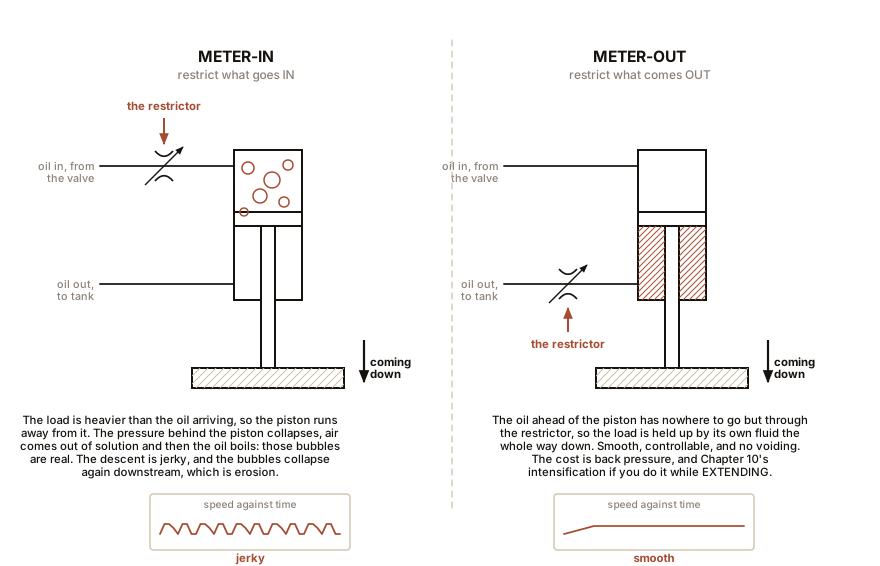
The obvious answer, and why it fails. Put an adjustable restrictor in the line feeding the cylinder, so only a trickle of oil goes in and the platform can only descend as fast as the trickle allows. That is called meter-in control and it works perfectly for a load that is resisting.
Against a load that is helping, it fails badly, and here is the mechanism. Gravity is trying to move the piston faster than the restrictor can fill the space behind it. So the piston runs away from the arriving oil, the pressure in that space collapses toward zero, and then below it: dissolved air comes out of solution and the oil begins to vaporise. The platform drops, the pressure recovers slightly, the platform stops, drops again. You get a jerky, uncontrolled descent, and it makes bubbles, which is exactly the aeration Chapter 7 says makes everything else worse.
The fix: meter the outlet. Put the restrictor on the line leaving the cylinder. Now the oil ahead of the descending piston has to be squeezed out through the restriction, so it builds a back pressure, and the load is held up by its own oil. The descent is smooth, and it is smooth because the controlled element is now the one gravity is fighting.
Meter-in  controls a load that pushes back.
Meter-out controls a load that could run away.
The rule, stated so it is easy to remember: if the load could move on its own, control what you let out, not what you put in.
And meter-out has a trap, which Chapter 11 named. Restricting the rod-side line while the cylinder is extending pressurises the small annulus with the force generated on the large piston face. With the reference cylinder at 10,000 kPa (1,450 psi) and no external load at all, the back pressure is:
19,630 N / 1,472 mm2 = 13.3 MPa = 13,300 kPa (1,930 psi)Add an assisting load of 5,000 N, which is what happens the instant the platform’s weight starts helping, and it becomes:
24,630 / 1,472 = 16.7 MPa = 16,700 kPa (2,420 psi)Sixty-seven percent above system pressure, and the relief valve cannot help, because the relief valve is watching the pump line and this pressure is being generated inside the cylinder. It bursts rod seals and hoses, and on a cylinder with a fat rod it is worse still. The fix is a small relief valve on the rod-side line, or a cylinder with a slimmer rod, or metering only where the load resists. Real machines do all three.
There is a third option worth knowing: bleed-off. Put the restrictor in a branch from the supply line back to tank, before the directional valve, so the surplus flow escapes there and the actuator gets the remainder. This is far more efficient than either of the others, because the pump now works at the load’s pressure rather than at the relief valve’s, and Chapter 8 says that is where the heat comes from. Its weakness is that all of the pump’s flow variation, and all of the pump’s own internal leakage change with pressure, shows up as speed variation in the actuator, so it is used where efficiency matters more than precision.
ON THE BENCH: Make cavitation happen in your hand
Parts: the 60 mL syringe; water; a thumb. Cost: nothing. Time: 3 minutes. Hazards: none. Method: fill the syringe with water and expel all the air. Block the tip hard with a thumb. Now pull the plunger out with real force. What you should see: bubbles appear inside the water, out of nowhere, growing on the barrel wall and in the body of the liquid. Release the plunger and they vanish. What you have just done: you dropped the absolute pressure inside the water low enough that dissolved air came out of solution, and if you pull harder, low enough that the water itself boiled at room temperature. That is what a runaway load does to a meter-in circuit, and it is what a starved pump inlet does to itself. The vapour bubbles then travel to a high-pressure region and collapse, which is why Chapter 21 calls cavitation an erosion problem rather than a flow problem. Do it once and you will never forget which side of a descending load to restrict.
Section 2: The Load That Must Not Sink
The problem. A platform must stay up for eight hours with the machine switched off, and it must not move more than a millimetre.
The obvious answer, and why it fails. Put the directional valve in a closed centre, which traps oil in both ends of the cylinder. Chapter 14’s Slow Down box already gave the answer: a spool valve does not seal, it merely fits. Internal leakage across a spool land at 10,000 kPa (1,450 psi) is typically 10 to 50 mL per minute, and on the reference cylinder’s 1,963 mm² (3.04 in²) piston, one litre of leakage is 509 mm (20 in) of travel. So 10 mL a minute is:
0.6 litres per hour = 306 mm per hour (12 in per hour)A foot an hour, on a valve that is working correctly. Spool valves hold loads for minutes, not for shifts.
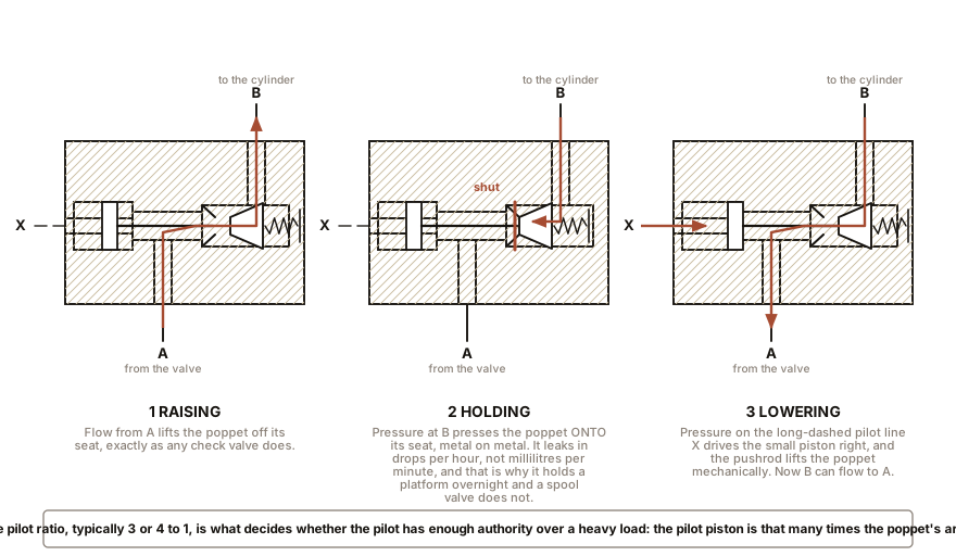
The fix: a pilot-operated check valve. An ordinary check valve is a poppet that seats metal on metal, or metal on a soft seal, and its leakage is measured in drops per hour rather than millilitres per minute. Put one in the line to the cylinder’s load-holding side and the load cannot come down.
Of course, now it cannot come down when you want it to either. So the check valve is given a pilot: a small plunger that, when pressure is applied from the opposite line, mechanically pushes the poppet off its seat. So the sequence is: to raise, flow pushes the poppet open normally. To hold, the poppet seats and nothing moves. To lower, pressure sent to the other end of the cylinder lifts the poppet and lets the oil out.
The number that matters is the pilot ratio, typically 3 to 1 or 4 to 1. A 3 to 1 valve holding 15,000 kPa (2,175 psi) needs 5,000 kPa (725 psi) on its pilot line to open. Choose too low a ratio and the pilot cannot open the valve against a heavy load; choose too high and the valve opens when it should not.
And the trap here is decompression. A pilot-operated check valve does not open gradually. It cracks, and the moment it cracks, a load that was being held by a solid column of oil is suddenly connected to a return line. On a large machine that produces a distinct lurch, and it can slam the poppet closed again as the pressure collapses, whereupon it re-opens, producing an audible chatter. The fix is a small decompression orifice in the poppet or a controlled pilot ramp, and the reason to mention it is that chatter on lowering is a symptom with a specific cause rather than a mystery.
Section 3: The Load That Must Come Down Gently
The problem. Same platform, but now it must descend at a controlled speed on demand, repeatedly, all day.
The fix: a counterbalance valve, which is a relief valve in the cylinder’s return line, set to a pressure slightly above what the load’s own weight generates. The load can only descend by pushing oil through that valve, and the valve throttles continuously.
How it differs from a pilot-operated check valve, which is the distinction people get wrong. A pilot-operated check valve is a switch: closed, or open. A counterbalance valve is a throttle: it is always partly open and always resisting. So the two do different jobs and a well-designed machine often has both, the counterbalance to control the descent and the check valve to hold the load when nothing is happening.
And a counterbalance valve is expensive in heat, which is worth stating plainly. Lower the reference cylinder’s 19,630 N load at 113 mm/s (4.5 inches per second) against 10,000 kPa (1,450 psi) of counterbalance and the flow leaving the cylinder is 10 litres/min (2.6 gal/min), so:
100 bar x 10 / 600 = 1.67 kWEvery watt of potential energy in that descending load, and then some, is being converted to heat in a valve. The load did work on the way down and you threw it away. This is why the current generation of excavators and cranes recover boom-down and load-lowering energy, either into an accumulator or through a hydraulic motor driving a generator, and why the saving is worth the complexity on a machine that lowers things thousands of times a day.
Section 4: Fast Approach, Slow Work
The problem. A press has a 400 mm (16 in) stroke, and for the first 350 mm (14 in) the tool is moving through air. Only the last 50 mm (2 in) does any work. At 85 mm/s (3.3 inches per second) the approach takes four seconds, all of it wasted, on every cycle.
The obvious answer, and why it is expensive. Fit a bigger pump. Four times the flow gives four times the speed, and it also gives you four times the motor, four times the heat when idling, and a machine that costs three times as much.
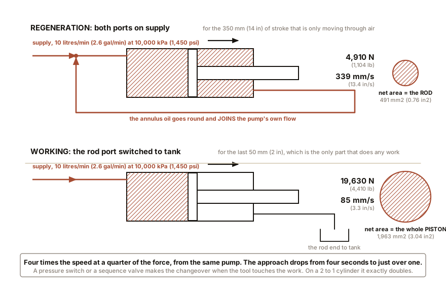
The fix: a regenerative circuit, which uses Chapter 11’s differential area as a feature rather than an annoyance.
Connect the rod-end port to the full-bore port, so that both sides of the piston see full supply pressure at once. The forces nearly cancel: the net push is now pressure acting only on the rod’s cross-section, because that is the area difference. And the oil pushed out of the annulus does not go to tank; it joins the supply and goes into the full-bore end. So the pump only has to supply the rod’s worth of volume.
On the reference cylinder:
net force  =  10 MPa  x  491 mm2   =  4,910 N     (1,104 lb)
speed      =  10 x 16,667 / 491    =  339 mm/s    (13.4 inches per second)
Four times the speed at a quarter of the force, from the same pump. The approach now takes just over one second. Then, when the tool touches the work, a pressure switch or a sequence valve switches the rod-end port over to tank, and the cylinder reverts to 85 mm/s (3.3 inches per second) and its full 19,630 N (4,410 lb) for the working stroke.
On a 2 to 1 ratio cylinder, where the rod area is exactly half the piston area, regeneration exactly doubles the speed and exactly halves the force, and those cylinders are made specifically for this circuit.
Section 5: This, Then That
The problem. A workpiece must be clamped, and only then drilled. Getting the order wrong destroys the tool and possibly the operator.
The fix: a sequence valve, which Chapter 12 introduced as a relief valve plumbed in series. Put it between the clamp cylinder and the drill feed cylinder, set above the clamp’s working pressure.
Numbers. A 32 mm (1.26 in) bore clamp cylinder has an area of 804 mm² (1.25 in²), and it needs 3,200 N (720 lb) of clamping force, so it needs 4,000 kPa (580 psi). Set the sequence valve at 5,000 kPa (725 psi).
Now trace what happens. The operator opens the valve. Oil goes to the clamp, which extends, and while it is moving the pressure is only whatever the clamp’s friction demands, perhaps 1,000 kPa (145 psi). The sequence valve stays shut, so no oil goes to the drill. The clamp reaches the workpiece and stops. Now the pressure rises, because Chapter 6 says pressure rises until the load moves and the load cannot move. It passes 4,000 kPa (580 psi), reaches 5,000 kPa (725 psi), and the sequence valve opens. Oil flows on to the drill feed, which advances.
The order cannot be got wrong, and there is not a single wire or sensor in the circuit. That is a beautiful piece of engineering and it is a hundred years old.
And now the honest caveat, because it is a real failure mode. A sequence valve responds to pressure, and pressure is not position. Suppose the workpiece is missing, or is undersized, or the clamp jams on a chip halfway. The clamp stops moving, the pressure rises to 5,000 kPa (725 psi) exactly as before, and the sequence valve opens the drill anyway. The circuit has confirmed that the clamp is pushing hard. It has not confirmed that the clamp is closed.
Where that distinction matters, you need a position signal: a limit switch, a proximity sensor or a magnetic reed switch on the cylinder body, and an electrical interlock. A pressure signal proves force. A position signal proves geometry. They are not interchangeable, and knowing which one a machine is relying on is a genuinely useful thing to notice about somebody else’s design.
IN PLAIN ENGLISH: A sequence valve is a door that only opens when the pressure behind it gets high enough, and the pressure only gets high when the first job has finished pushing. So the second job automatically waits for the first. The catch is that it waits for the pushing to be finished, not for the job to be done, and if something jams then the pushing finishes early.
Section 6: Two Things at Once
The problem. One pump, two actuators, and the operator wants both to move. Chapter 6 established the ugly truth: with unequal loads, the light one takes nearly all the flow and the heavy one barely moves.
Three fixes, in increasing order of sophistication and cost.
A priority valve guarantees a set flow to one function before any goes to the others. This is what a wheeled loader does with its steering: steering gets its flow first, always, because a machine that cannot steer is a great deal more dangerous than a machine that cannot lift. Everything else shares what is left.
A flow divider splits the pump’s flow into two fixed proportions regardless of the two loads, typically holding 50:50 within 5 to 10 percent. It is a spool with two matched orifices and a self-centring action, and it is simple and reasonably cheap. Its cost is heat, because the function with the lighter load has its surplus pressure throttled away.
Pressure-compensated valve sections, which is what modern mobile machinery uses. Each section of the control valve contains its own small compensator that holds a constant pressure drop across that section’s metering notch, exactly like the pressure-compensated flow control of Chapter 12. So each actuator’s speed depends only on how far the operator moved that lever, and not on its own load nor on what the other actuators are doing.
And the distinction that matters when the pump runs out, which is called saturation. In a pre-compensated valve, when the demand exceeds what the pump can supply, the sections with the lighter loads win and the heaviest function stops. In a post-compensated valve, sometimes called flow sharing, all the sections reduce proportionally, so every function slows down together and none of them stops. From the operator’s seat, post-compensated feels like a machine that is working hard, and pre-compensated feels like a machine that is broken. Chapter 16 is about what that difference is like on an excavator.
ON THE BENCH: Measure your own load-holding leakage
Parts: the bottle jack from Chapter 5; a heavy load such as a car corner; a fine felt pen or a dial indicator if you have one; axle stands; four hours of not paying attention. Cost: nothing. Time: four hours of waiting. Hazards, and read this one twice. Put axle stands under the car so that if the jack fails nothing falls. The whole point of this test is to see the jack lose pressure, so treat it as a machine that is going to. Never be under the vehicle. Chock the wheels. Level ground. Method: lift the corner, fit the axle stands to catch it but leave a small gap so the jack is still carrying the load, and mark the ram against the body with a fine line. Check the mark at 15 minutes, one hour and four hours. What you should see: on a good jack, no movement you can measure with a pen line, and perhaps 0.1 to 0.5 mm (0.004 to 0.02 in) on a dial indicator over four hours. On a tired jack, a visible sink of several millimetres, and the culprit is nearly always the small check valve between the pump and the ram, held off its seat by a speck of debris. Why this is the chapter’s experiment: a bottle jack holds its load with a poppet check valve, and this test measures how well a poppet seals. Compare your result with this chapter’s arithmetic for a spool valve, which sinks 306 mm (12 in) an hour. Poppets seal and spools do not, and you have now measured both ends of that statement. Better, if you have one: a dial indicator on a magnetic base against the ram makes the reading unambiguous, and it turns a subjective test into a number you can write down and repeat next year.
SLOW DOWN. Check Your Understanding: A scissor lift uses a meter-out restrictor for its descent, plus a pilot-operated check valve for load holding, and it works perfectly. The machine is then modified to carry a heavier platform, and the counterweight is increased. Now, on a cold morning only, the descent is jerky for the first few seconds and then becomes smooth. Nothing leaks and nothing has broken. What is happening? Answer before reading on.
The oil is thick, so the meter-out restrictor is passing less flow than it does warm, so the descent is slower than the pilot-operated check valve’s pilot ratio was chosen for. Follow it through. Descending requires the pilot check to be held open by pressure from the opposite line. That pressure is generated by the pump pushing oil into the other end of the cylinder. But the cylinder is descending slowly, so it is only accepting a trickle, so the pump’s flow mostly goes over the relief and the pilot pressure is fine. So far so good, and that is not the fault.
The fault is that the descent is now slow enough for the check valve to close. A pilot-operated check valve near its opening threshold with a heavy load and a cold, viscous, restricted return will crack, let a little oil past, see the pressure momentarily drop as the load settles, and close again. Then the pilot pressure rebuilds and it cracks again. That is the chatter described in Section 2, brought on by the combination of a heavier load and thicker oil, and it explains why it happens only when cold and only since the modification.
The three real fixes, and it is worth noticing that none of them is a new part on the descent line: open the meter-out restrictor to suit the heavier load, which is the adjustment the modification should have included; fit a check valve with a higher pilot ratio, so the pilot has more authority over a heavy load; or use a high-viscosity-index oil per Chapter 9 so that the cold behaviour is closer to the warm. And the general lesson: when a machine is modified, the numbers that were chosen for the old load are all still set for the old load, and the components that fail first are the ones whose settings were a compromise to begin with.
You can read a circuit and you can build one that solves a real problem. The next four chapters take that skill to four real machines and ask, in each case, why the designer chose the fluid they chose.

Bench Degree
Get the degree without the diploma.
Learn the material, not how to pass the exam.