Bench Degree·FLUID POWERchapter
Chapter 16: The Excavator
Forty tonnes of force out of a cylinder you could carry, controlled by a joystick that moves under two fingers. And the reason it is not pneumatic is one line of arithmetic.
Take a 20 tonne (44,000 lb) tracked excavator, which is the size that digs a house foundation and the commonest machine of its type in the world. Its numbers, roughly, across manufacturers:
- Operating weight: 20,000 kg (44,000 lb).
- Engine: about 110 kW (148 hp) diesel.
- Main pumps: two variable-displacement axial piston pumps on a common shaft, together delivering up to about 220 litres/min (58 gal/min).
- Working pressure: 35,000 kPa (5,075 psi), with a momentary boost function to around 38,000 kPa (5,510 psi).
- Boom cylinder: 120 mm (4.7 in) bore, 85 mm (3.3 in) rod, 1,300 mm (51 in) stroke.
- Bucket digging force: around 110 kN, which is 11 tonnes-force or 24,700 lb, at the teeth.
- Cooler: sized to reject roughly 30 kW.
Everything in this chapter comes out of those figures.
Section 1: Why It Is Not Pneumatic, in One Calculation
The boom cylinder’s piston area is:
0.7854 x 120 x 120 = 11,310 mm2 (17.5 in2)At 35,000 kPa (5,075 psi) that gives:
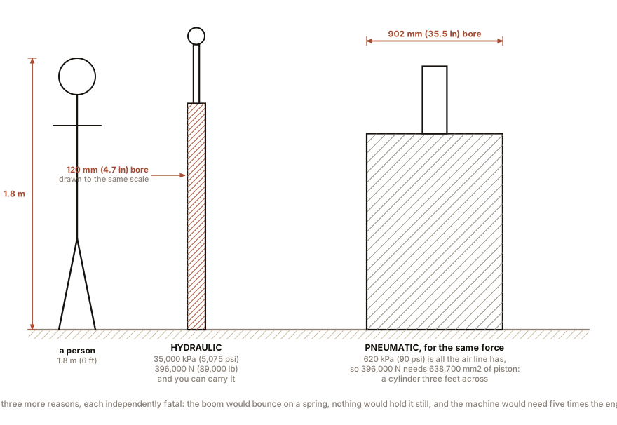
35 MPa x 11,310 mm2 = 396,000 NThree hundred and ninety-six kilonewtons: 40 tonnes-force, or 89,000 lb, out of a cylinder about 1.7 m (5.6 ft) long that two people can lift.
Now suppose you wanted to do that with shop air at 620 kPa (90 psi). The area required is:
396,000 N  /  0.62 N per mm2  =  638,700 mm2
diameter  =  902 mm   (35.5 in)
A cylinder nearly a metre across, three feet in diameter, to replace one you can carry. That is the answer, and it is complete on its own. But there are three more reasons and each one is independently fatal.
The boom would sag and bounce. Chapter 7’s arithmetic: air’s bulk modulus is its own pressure, so a cylinder of 900 mm (35 in) bore full of air is a spring, and an excavator boom on a spring cannot be positioned. Every bucket load change would move the boom, and the operator would be fighting an oscillation rather than digging.
Nothing would hold. An excavator regularly holds a full bucket stationary in mid-air. A pneumatic cylinder holds nothing, because Chapter 13’s leakage plus Chapter 7’s compressibility means the position depends on the load.
And the machine would have to carry a compressor. A hydraulic pump takes shaft power from the engine at 90 percent efficiency. Compressing air to 620 kPa (90 psi) and using it in a cylinder recovers around 20 percent, which Chapter 17 works out in detail, so the same digging force would need five times the engine.
Section 2: The Pump Cannot Deliver Its Own Rating, and That Is Deliberate
Multiply the headline numbers together and something does not add up.
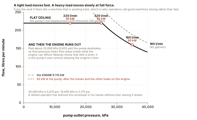
350 bar x 220 litres/min / 600 = 128 kW (172 hp)The pumps could absorb 128 kW and the engine makes 110 kW. So if the operator ever demanded maximum flow at maximum pressure, the pumps would stall the engine.
They do not, because the pumps have a total power control, also called a horsepower or torque limiter. Each pump’s displacement control watches the system pressure and destrokes the pump as the pressure rises, so that the product of pressure and flow stays inside what the engine can supply. The pump’s operating envelope is a hyperbola.
So the machine has, in effect, gears:
| System pressure | Total flow available | Hydraulic power |
|---|---|---|
| 15,000 kPa (2,175 psi) | full 220 litres/min (58 gal/min) | 55 kW |
| 25,000 kPa (3,625 psi) | about 220 litres/min (58 gal/min) | 92 kW |
| 35,000 kPa (5,075 psi) | limited to about 160 litres/min (42 gal/min) | 93 kW |
A light load moves fast; a heavy load moves slowly at full force. Nobody chose that with a lever. It is the pump’s own control, obeying the engine’s limit, and from the seat it feels exactly like a machine that is working hard, which is why operators describe good machines as feeling strong rather than feeling fast.
And this is the same idea as Chapter 10’s load-sensing pump with one extra constraint added. A load-sensing pump gives the operator the flow he asks for. A power-limited load-sensing pump gives him the flow he asks for until the engine cannot afford it, and then reduces everybody proportionally.
Section 3: Why the Joysticks Are So Light
Chapter 12 established that a solenoid cannot move a large spool against flow forces. The same is true of a human hand, and worse.
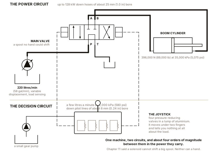
The main control valve on a 20 tonne machine handles up to 220 litres/min (58 gal/min) at 35,000 kPa (5,075 psi). Its spools are 30 to 40 mm (1.2 to 1.6 in) in diameter, and the flow forces on them at full flow run to several hundred newtons. A direct mechanical linkage to that valve would need a lever you pulled with both hands, and it would kick. Machines were built that way until the 1970s and operators had the forearms to prove it.
The modern arrangement is a two-stage hydraulic control, and it is elegant.
A small separate gear pump makes a pilot supply at around 4,000 kPa (580 psi), at a few litres a minute. The joystick is not a lever at all: it is four small pressure-reducing valves in a block, one per direction. Push the stick and its cam depresses a plunger which compresses a spring which sets the outlet pressure of one reducing valve in proportion to how far you moved it. That pilot pressure travels down a small-bore line to the end of the main spool and pushes it.
So:
- The operator’s hand works against a small spring, a few newtons, and feels nothing of the load.
- The stick’s displacement sets a pilot pressure, which sets the main spool’s position, which sets the flow, which sets the speed. Proportional control, entirely hydraulic, no electronics required.
- The stick self-centres because the spring pushes it back and the main spool has its own centring springs.
- And it is inherently fail-safe: lose the pilot pressure and every main spool springs to centre.
The feel is set by the springs in the joystick block, which is why two machines with identical hydraulics can feel completely different from the seat, and why operators are particular about brands in a way that looks like superstition and is not.
Newer machines replace the pilot lines with wires: the joystick becomes an electrical potentiometer and the main spool is moved by a proportional solenoid, which is Chapter 12’s proportional valve. That buys programmability, work-mode selection, and the ability to put limits in software. It also means the machine no longer moves when the electronics are unhappy, which is a real trade rather than an improvement.
Section 4: Two Functions at Once, and What Saturation Feels Like
An operator digging a trench is moving three or four functions simultaneously, all the time. Chapter 6 showed why that is hard and Chapter 15 gave the three fixes. Here is how a real machine uses them.
Two pumps, split into two groups. Typically one pump serves boom, one track motor and the bucket; the other serves the arm, the other track and the swing. That split alone solves most of the conflict, because the functions used together most often are on different pumps.
A confluence or summation valve joins the two pumps’ flow for functions that need more than one pump can supply, which is boom-raise and fast travel.
A straight-travel valve, which is a small circuit that exists solely because of Chapter 6’s problem. When both tracks are being driven and the operator also uses a work function, the work function steals flow from one track and the machine curves off course. The straight-travel valve reconnects the two track motors in a way that keeps them fed equally, and the machine walks straight.
Pressure-compensated valve sections, so each function’s speed follows its lever rather than its load.
And here is what saturation feels like, because it is the operator’s whole experience of the hydraulics. When the total demand exceeds what the pumps can supply at that pressure:
- On a pre-compensated valve, the lightest load wins and the heaviest function stops. Curl the bucket while raising a loaded boom and the boom stops dead. Operators call this the machine “dropping a function”, and it is unnerving.
- On a post-compensated, flow-sharing valve, every function slows in proportion. Nothing stops. The machine feels like it is straining rather than failing, and that is the modern behaviour.
A skilled operator manages saturation continuously without thinking about it, feathering the lever on the function that matters least. What they have learned, in their hands, is the pump’s power curve.
Section 5: Holding the Boom Up
An excavator holds loads in the air constantly, and a spool valve leaks, which Chapter 14 quantified as 306 mm (12 in) an hour on a small cylinder. On a boom cylinder holding a bucket over a person’s head, that is unacceptable, and in most jurisdictions it is also illegal for a machine rated to lift.
So boom and arm cylinders carry load-holding valves, which are Chapter 15’s pilot-operated check valves bolted directly to the cylinder port rather than plumbed into the valve block. Directly on the cylinder is the whole point: a check valve at the valve block protects against spool leakage but not against a burst hose, and a hose is the component most likely to fail. A holding valve screwed into the cylinder’s own port means that if the hose bursts, the load stops where it is.
These valves are also why an excavator’s boom lowers with a distinct feel. The pilot has to open the check valve before anything moves, which introduces a small threshold, and Chapter 15 explained the chatter that follows if the pilot ratio is wrong for the load.
And this is the place to notice the machine’s real load-holding weakness, which is not the valves. Chapter 7: the oil compresses about 1.4 percent at 35,000 kPa (5,075 psi), and the hoses swell more than that. A 20 tonne machine’s boom circuit might hold 8 litres (2.1 gal) of pressurised oil, so about 110 mL of the oil in it is compression, plus a similar amount of hose stretch. On the boom cylinder’s 11,310 mm² (17.5 in²) piston, 220 mL is about 20 mm (0.79 in) of cylinder movement, and through the boom’s linkage that is more at the bucket. So the machine settles a couple of centimetres when a load is applied, and it is not leaking. It is the fluid and the hoses being elastic, exactly as Chapter 7 said, and no amount of valve replacement will change it.
IN PLAIN ENGLISH: An excavator is one engine turning two pumps, and the pumps automatically make less flow when the pressure rises so they never ask the engine for more than it has. The joysticks do not move the big valves; they send a small pressure down a thin pipe that moves the big valves for you, which is why they are so light. And the boom stays up because of a small one-way valve screwed into the cylinder itself, so that even a burst hose leaves the load where it is.
ON THE BENCH: Measure a machine’s pump flow from outside it, with a tape measure and a stopwatch
Parts: a tape measure; a stopwatch or phone; an excavator, backhoe, tractor loader or skip lorry, and an operator willing to help for ten minutes. Cost: nothing. Time: 30 minutes. Hazards: stand where the operator can see you and where nothing can swing over you. Agree hand signals before starting. Never approach a machine with the engine running without eye contact. Do all measuring with the engine off and the boom on the ground. Method, in three steps. 1. With the machine shut down and the boom resting on the ground, measure the boom cylinder’s outside barrel diameter and subtract twice the wall thickness, or better, read the bore off the plate or the parts book. Measure the stroke by measuring the exposed rod fully retracted and fully extended. 2. Compute the cylinder’s swept volume. For 120 mm (4.7 in) bore and 1,300 mm (51 in) stroke:
11,310 mm2 x 1,300 mm = 14,700,000 mm3 = 14.7 litres (3.9 gal). 3. Now have the operator raise the boom from fully down to fully up, at full lever, on high idle, with no load in the bucket, and time it. Repeat three times and take the fastest. The arithmetic: if the boom raises in 4.0 seconds:14.7 litres / 4.0 s x 60 = 220 litres/min (58 gal/min)What you should see: a figure within 10 or 15 percent of the machine’s published pump flow, which you can then look up and check. You have measured the output of a 128 kW hydraulic system with a tape measure, and you did it by inverting Chapter 6’s speed equation. What to notice, and it is the interesting part: do it again with a full bucket. The time gets longer, because the pressure is higher, because the pump’s power control has destroked it. You have just plotted one point on the pump’s power curve from the driver’s seat.
ON THE BENCH: Feel a pilot circuit, and find the holding valves
Parts: a machine, permission, and a torch. Cost: nothing. Time: 20 minutes. Hazards: engine off, key out, boom on the ground, and on most machines the pilot circuit has an accumulator, which per Chapter 13 stays charged. Many machines are designed so that the joysticks can be worked for a few movements after shutdown, precisely because that accumulator is holding pressure. Treat every joystick as live and every hose as pressurised. Do not undo anything. Method: with the machine dead and the boom down, move a joystick through its full travel and note the force. Then find the main control valve block, which is a heavy iron casting under the cab floor or behind a side panel with a great many hoses on it, and find the small-bore pilot lines going to the ends of its spools: they are typically 6 mm (0.24 in) lines among 25 mm (1.0 in) hoses. Then trace one boom cylinder hose to the cylinder port and look for a valve body bolted to the cylinder itself. That is the load-holding valve of Section 5. What you should conclude: the machine has two hydraulic systems, one carrying power and one carrying decisions, and the difference in hose size is the difference between Chapter 14’s continuous line and its long-dashed pilot line. You are now looking at a circuit diagram in three dimensions.
SLOW DOWN. Check Your Understanding: An excavator’s boom raises normally when the bucket is empty but is very slow with a full bucket, and the engine note does not change. A mechanic says the pump is worn. Another says the relief valve is set low. A third says nothing is wrong. Using this chapter, decide which is most likely and name the single measurement that would settle it. Answer before reading on.
The third is most likely, and the machine is behaving exactly as designed. The boom with a full bucket demands high pressure, and Section 2 says the pump’s total power control destrokes it as the pressure rises so as not to stall the engine. So the flow falls, so the boom slows. And the engine note not changing is the clue that confirms it: the whole purpose of the power control is to keep the engine inside its capability, so a correctly working machine does not bog down. A machine whose engine note drops under load has a power control that is failing to limit, which is the opposite fault.
Why the other two diagnoses are worth taking seriously anyway. A worn pump also gets slower under load, for Chapter 10’s reason: internal leakage rises with pressure. A relief valve set low would cause the boom to stop rather than slow, because the pressure could not reach what the load demands.
The measurement that settles it is a flow test at two pressures, which is Chapter 21’s ten-minute test: measure the delivered flow at low pressure and at working pressure, and compare the drop with the manufacturer’s published power curve. If the flow follows the published curve, the machine is healthy. If it falls below the curve, the pump is worn. One instrument, two readings, and three opinions resolved. And note what made this diagnosable: the manufacturer publishes the curve, so there is a specification to measure against. Diagnosis is nearly always the comparison of a measurement with a number somebody wrote down, and where nobody wrote the number down, diagnosis becomes argument.
An excavator is what fluid power looks like when the requirement is force. The next chapter is what it looks like when the requirement is speed, cleanliness and being safe to stand next to, and the fluid changes.

Bench Degree
Get the degree without the diploma.
Learn the material, not how to pass the exam.