Bench Degree·FLUID POWERchapter

Chapter 14: The Symbol Language
Every fluid power symbol is a picture of what the component does, not an arbitrary badge to be memorised. Learn the eight rules that generate them and you can read a diagram you have never seen before.
Somewhere on every hydraulic and pneumatic machine there is a circuit diagram, usually printed on a plate inside an access panel or folded into the back of a manual. It is the most useful document on the machine, and most people who operate and even maintain such machines cannot read it.
They think it is a code to be memorised. It is not. The standard, ISO 1219, was built so that each symbol is a schematic drawing of the component’s internal function. Once you know the eight conventions in this chapter, you can look at a symbol you have never seen, work out what the thing inside must be doing, and be right.
This is the literacy chapter, and it is the one that turns everything before it into a usable skill.
Section 1: Lines, and Which Ones Carry Anything
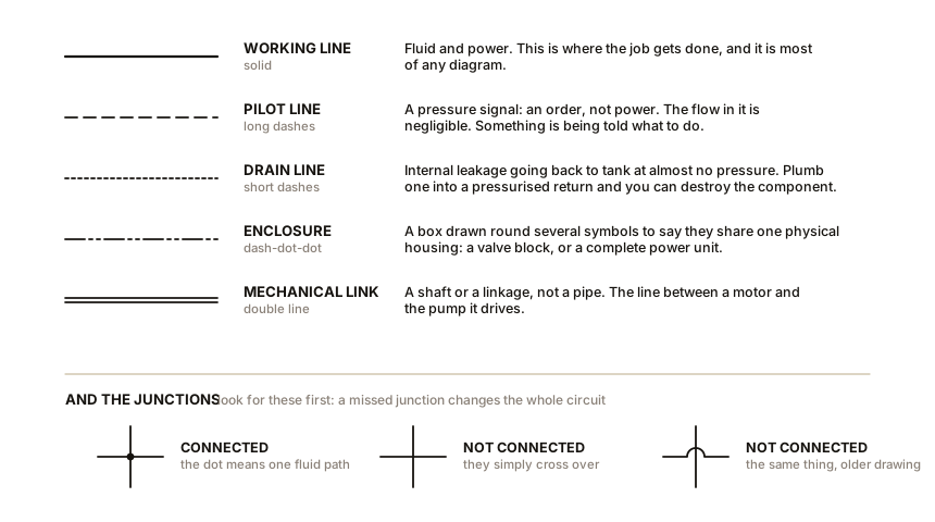
Five kinds of line, and getting these wrong is the commonest reading error.
A continuous solid line is a working line. Fluid flows through it and does the job. Most of the diagram.
A long-dashed line is a pilot line. It carries pressure as a signal, not as power. The flow in it is negligible. Every time you see a long-dashed line you are looking at something being told what to do.
A short-dashed line is a drain or leakage line. It returns the small internal seepage from a valve or pump case back to tank at near-zero pressure. A drain line that has been plumbed into a pressurised return can destroy the component it drains, which is a real installation error and one reason to know which line is which.
A chain line, dash-dot-dot, is an enclosure. It draws a box around several symbols to say “these are all inside one physical housing”, which is how a valve block or a complete power unit is shown.
A double line is a mechanical connection: a shaft between a motor and a pump, or a linkage between two valve spools.
And junctions. Lines that cross with a dot are connected. Lines that cross with no dot simply pass over one another. On old drawings a small hop or bridge is used instead. Look for the dots first, because a missed junction changes the whole circuit.
Section 2: Circles Are Rotary, Squares Are Valves
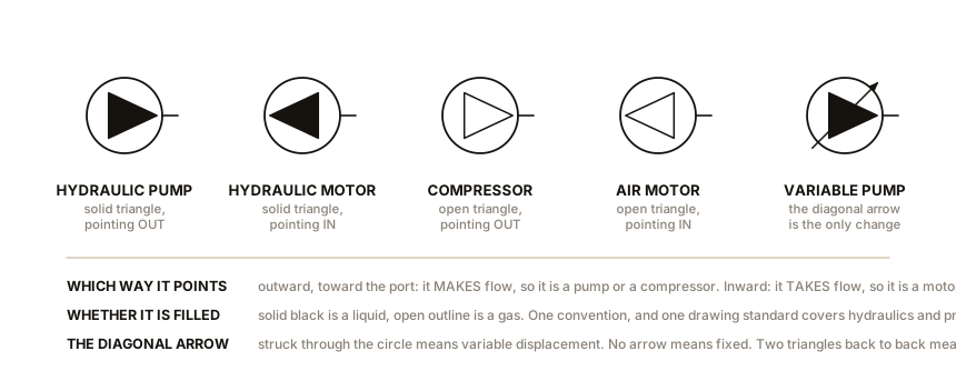
A circle is a rotary machine: a pump, a motor, or a compressor.
Inside the circle goes a triangle, and the triangle carries two pieces of information.
Which way it points tells you which kind of machine it is. A triangle pointing outward, toward the port, is pushing fluid out: that is a pump. A triangle pointing inward is receiving fluid: that is a motor. Two triangles pointing opposite ways means the machine can do either, which is what a hydrostatic transmission needs.
Whether it is filled tells you the fluid. A solid black triangle means a liquid. An open outline triangle means a gas. So the same circle with a solid triangle is a hydraulic pump and with an open triangle is a compressor or an air motor. That single convention lets one drawing standard cover both halves of this book, and it is the neatest thing in ISO 1219.
An arrow drawn diagonally across the circle means variable displacement. No arrow means fixed. So Chapter 10’s pressure-compensated piston pump is a circle, a solid triangle pointing out, and a diagonal arrow through it, and if the compensator is shown it appears as a small pilot line from the outlet back to the arrow.
A square, or a row of squares, is a valve. And here is the rule that makes valve symbols readable:
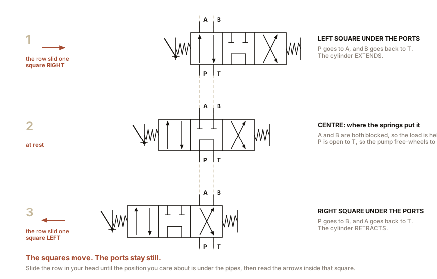
Each square is one position of the valve, and the ports are drawn attached to the square the valve is currently in.
So a 4/3 directional valve is three squares in a row, with the four ports drawn on the middle one, because that is where the valve rests. Inside each square, arrows and blocked-off T shapes show what is connected to what in that position.
To read it, imagine sliding the row of squares sideways under the fixed ports. Shift the row one square to the left and the ports now line up with the left-hand square’s internal arrows, and that is what the valve does when actuated that way. This is the single most important trick in reading these diagrams and nobody ever states it plainly. The squares move; the ports stay still.
Section 3: How a Valve Gets Told What to Do
The symbols on the ends of the row of squares are the actuation, and they are literal pictures.
- A spring, drawn as a zigzag, means the valve returns to that position on its own. A spring on both ends means spring-centred.
- A lever, drawn as a diagonal line with a pivot, means a hand lever.
- A pedal, drawn as a foot shape, means what it looks like.
- A plunger or roller, drawn as a stem with a circle, means the valve is tripped mechanically by the machine’s own motion.
- A solenoid, drawn as a small rectangle with a diagonal line inside it, is an electromagnet.
- A pilot, drawn as a small open rectangle or a triangle, means pressure moves it. Combine solenoid and pilot on the same end and you have Chapter 12’s pilot-operated solenoid valve, and the symbol says so.
- A detent, drawn as a small notch, means it stays where you put it.
So the actuation symbols on both ends plus the centre condition tell you, without any text, exactly how the machine behaves when the operator lets go. A valve with a solenoid one end, a spring the other, and a closed centre is a two-position valve that snaps shut on power failure. A valve with levers both ends and a detent is one that stays where the operator left it, forever, including overnight.
Section 4: Pressure Valves, and the Offset That Means “Normally Closed”
Pressure valve symbols are one square with three things attached: a flow arrow, a spring, and a pilot line.
The trick is that the arrow is drawn offset from the ports. In the resting position, the arrow does not line up with the two lines, so nothing flows. The pilot line comes from wherever the valve is sensing, and it pushes against the spring. When the pressure wins, the square shifts, the arrow lines up, and flow passes.
So the symbol is a moving picture of a spring being beaten by a pressure. And once you see that, all four pressure valves from Chapter 12 differ only in where the pilot line comes from and whether the valve is drawn normally open or normally closed:
- Relief valve: normally closed, pilot from the inlet, outlet to tank.
- Sequence valve: normally closed, pilot from the inlet, outlet onward to the next actuator. The symbol is nearly identical to a relief valve and the difference is what the outlet is connected to, which is exactly the point Chapter 12 made in words.
- Pressure-reducing valve: normally open, so the arrow lines up at rest, pilot from the outlet, closing as the outlet rises.
- Counterbalance valve: normally closed, pilot from the inlet, in a return line, usually with a check valve drawn beside it to allow free flow the other way.
And two very common small symbols:
A check valve is a ball sitting in a seat, drawn as a circle resting in a V between two lines. Flow pushes the ball off the seat one way and onto it the other. Add a light spring behind it and it becomes a cracking-pressure check. Add a long-dashed pilot line and a small plunger and it becomes the pilot-operated check valve of Chapter 15.
An adjustable restrictor is a line with a diagonal arrow through it. A fixed one has no arrow. A pressure-compensated flow control adds a second square with its own spring and pilot, because that is exactly what is inside it.
Section 5: The Rest of the Alphabet
A cylinder is a rectangle with a piston and a rod. One port means single acting. Two ports means double acting. A rod out of both ends means double rod. Two short lines drawn inside the barrel at each end mean cushions. A telescopic cylinder is drawn as nested rectangles.
A reservoir is a rectangle open at the top, drawn with three sides. Where the line ends matters: a line stopping above the open top returns above the oil level, and a line drawn down inside it returns below the level, which Chapter 13 says is what you want.
A filter is a diamond with a dashed line across the short axis. A cooler is a diamond with two solid arrows pointing outward, and a heater is a diamond with arrows pointing inward, which is delightfully literal.
An accumulator is a tall oval with a line or curve across it separating gas from liquid, and a small gas-charge symbol at the top.
A pressure gauge is a circle with a needle. A pressure switch is a small square with a pilot line and an electrical contact. A flow meter is a circle with a rotor.
A quick-release coupling is drawn as two facing brackets, and a self-sealing one adds two check valves, which is why disconnecting one under pressure is a bad idea.
And the port letters. Hydraulics uses letters: P for pump, T for tank, A and B for actuator ports, X and Y for external pilot and pilot drain, L for a case drain. Pneumatics uses numbers instead: 1 for supply, 2 and 4 for outputs, 3 and 5 for exhausts, and 12 and 14 for the pilots that shift the valve toward port 2 or port 4 respectively. Those two-digit pilot numbers are not arbitrary: 14 means “the pilot that connects 1 to 4”. Knowing that has saved a great many hours of staring at a pneumatic manifold.
Section 6: Now Draw the Machines You Have Already Built
ON THE BENCH: Draw the two-syringe press as a proper circuit
Parts: paper, a pencil, and the rig from Chapter 1. Cost: nothing. Time: 20 minutes. Hazards: none. Method: draw the rig using only the symbols in this chapter, then check your drawing against the list below. What it should contain: two cylinder symbols, both single acting, connected port to port by a single continuous working line. No pump, no valve, no reservoir, no relief valve. And now the useful part: look at what is missing and say why each absence matters. - No pump. So the stroke is finite, which is exactly the limitation Chapter 1 Section 5 identified. - No reservoir. So there is nothing to make up losses and no place for air to escape, which is why bleeding it was so fiddly. - No relief valve. So the pressure limit is whatever the weakest joint is, and Chapter 10 says why that is unacceptable in a real machine. - No directional valve. So the only way to reverse it is to push the other plunger. What you have learned: a circuit diagram is a checklist. The value of drawing one is mostly in the components you find yourself unable to draw.
ON THE BENCH: Draw the bottle jack, and then the reference circuit
Parts: paper and pencil; the bottle jack from Chapter 5 if you have it. Cost: nothing. Time: 40 minutes. Hazards: none. Method, part one: the jack. Draw it from what you know it must contain, then take the jack’s filler plug out and confirm. It needs: a reservoir; a hand-operated single-acting pump, drawn as a small cylinder with a lever; two check valves, one between reservoir and pump so oil can be drawn in but not pushed back, and one between pump and ram so oil can be pushed in but not come back; the ram as a single-acting cylinder; and a manual release valve from ram back to reservoir, which is the knob you turn to lower the load. Six symbols, and that is a complete and correct hydraulic circuit. It also explains the machine: the two check valves are what makes a reciprocating hand pump work at all, and the release valve is why the load comes down when you turn the knob and not before. Method, part two: the reference circuit used throughout this book. Draw a motor-driven fixed-displacement pump of 7 cm³ per revolution (0.43 in³), a relief valve set to 10,000 kPa (1,450 psi), a 4/3 lever-operated valve with a tandem centre, an adjustable flow control on the A line, a 50 mm (2.0 in) bore cylinder, a return filter, and a reservoir. Then check your drawing against Chapter 8’s table and confirm you can trace where each of the three heat sources is, and where the useful 200 W goes. A diagram you can compute from is a diagram you have understood.
ON THE BENCH: Find a real diagram and trace it
Parts: a real machine and permission to look at it. A skip lorry, a farm tractor, a scissor lift, a workshop press, a bin lorry, a log splitter, a garage two-post ramp. A phone camera. Cost: nothing. Time: an hour, and it is the hour that makes this chapter worth reading. Hazards: the machine must be off, isolated, and with any accumulator discharged, per Chapter 13. Read, do not touch. Never run a hand along a line. Method: find the diagram, which is usually on the inside of a panel door, on the tank, or in the manual. Photograph it. Then, working on the photograph rather than the machine, answer these six questions in order. 1. Find the pump. Fixed or variable? Is there a diagonal arrow? 2. Find the relief valve and read its setting. That is the machine’s maximum pressure and every force it makes derives from it. 3. Find the directional valves and identify their centre conditions. Then say what the machine does when the operator releases every lever at once. 4. Find every restrictor. Each one is a heat source, and Chapter 8 says how big. 5. Find any accumulator. If there is one, find its discharge valve on the actual machine before you go any further. 6. Pick one cylinder and compute its force, from the relief setting and the bore, which is usually stamped on the cylinder or in the parts list. What you should find: that a diagram you could not read an hour ago now yields all six answers in about fifteen minutes, and that answer three surprises you.
IN PLAIN ENGLISH: A fluid power diagram is a map of where the fluid can go, drawn with pictures of what each part does inside. Circles spin. Squares switch. Springs push things back. Dashed lines carry orders rather than power. And a valve’s picture shows every position it has, side by side, so you read it by sliding the picture along under the pipes until the pipes line up with the position you care about.
SLOW DOWN. Check Your Understanding: You are handed a diagram showing a fixed-displacement pump, a relief valve, and a single 4/3 solenoid valve with a closed centre and springs on both ends, feeding one cylinder that raises a heavy platform. There is no accumulator and no counterbalance valve. The machine has been in service for ten years. Name the two things this diagram tells you will happen, one of them daily and one of them eventually. Answer before reading on.
Daily: the oil overheats whenever nobody is touching the controls. Springs on both ends with a closed centre means the valve returns to centre when de-energised, and a closed centre blocks the pump, so the full flow goes over the relief valve at full pressure. That is Chapter 12’s arithmetic and Chapter 8’s temperature rise, and it is happening every time the operator pauses.
Eventually: the platform sinks. A closed-centre spool valve holds the load by trapping oil between two spool lands, and a spool land is a sliding clearance, not a seal. Internal leakage across a land at 10,000 kPa (1,450 psi) is typically 10 to 50 mL per minute, which sounds trivial and is 0.6 to 3 litres (0.16 to 0.79 gal) an hour. On the reference cylinder’s 1,963 mm² (3.04 in²) piston, one litre is over 500 mm (20 in) of travel. So the platform comes down on its own, slowly, and it does it faster as the valve wears. The fix is the pilot-operated check valve of Chapter 15, which seals metal on metal instead of by clearance.
And the real lesson: both of those faults are visible in the diagram and neither is visible in the machine. Nobody watches a platform for an hour, and a warm tank looks like a working tank. Reading the drawing tells you what to go and measure.
You can read the language. The next chapter uses it, taking six real problems and building the circuit that solves each one, so that the diagrams stop being descriptions and start being arguments.

Bench Degree
Get the degree without the diploma.
Learn the material, not how to pass the exam.