Bench Degree·FLUID POWERchapter

Chapter 13: Storing and Conditioning
A hydraulic accumulator stores its energy in nitrogen, because oil cannot store any. And the small cylinder bolted to the side of a machine holds full system pressure after the key is out, which is the second of this volume’s two genuine killers.
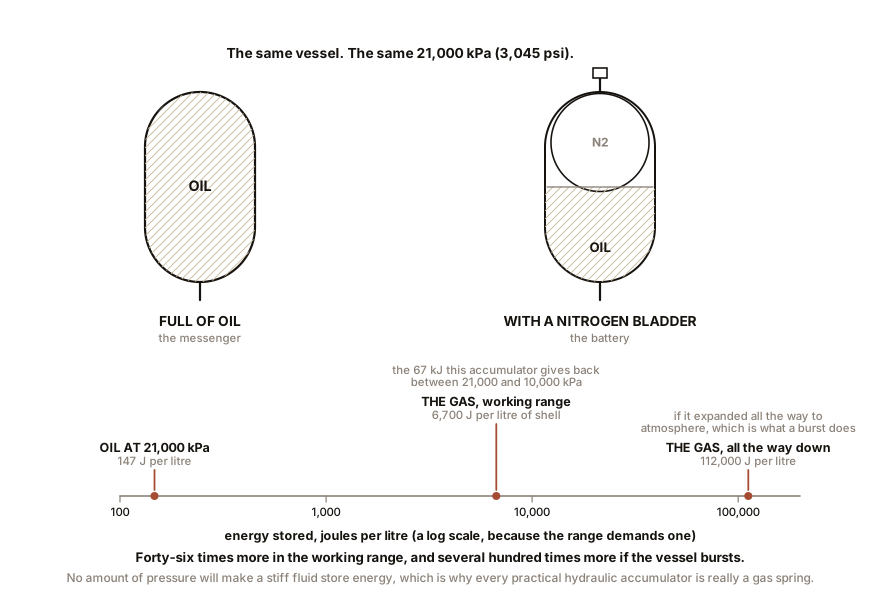
Chapter 7 gave the number: one litre of oil at 21,000 kPa (3,000 psi) stores about 147 joules, and one litre of air at a twenty-sixth of that pressure stores 896 joules. A stiff fluid is a poor spring, and a poor spring is a poor battery.
So every practical hydraulic accumulator is really a gas accumulator with oil as its messenger. The oil transmits the pressure and does the work; the gas holds the energy. Understanding that one sentence makes every accumulator specification and every accumulator hazard obvious.
Section 1: The Four Kinds of Accumulator
Bladder. A steel shell containing a rubber bladder filled with nitrogen. Oil enters below the bladder and squeezes it. The bladder is light, so the response is fast, and there is no sliding seal to leak. This is the commonest type by a wide margin. Its limit is bladder life: the rubber must not be inverted or over-stretched, which sets rules on the pressures, below.
Piston. A free-floating piston in a bore, gas on one side and oil on the other. Tolerates a much wider pressure ratio and higher temperatures, is repairable, and is used where the duty is severe. It has a sliding seal, so it can leak gas into the oil slowly, and the piston’s mass makes it slower to respond.
Diaphragm. A small welded shell with a rubber diaphragm, typically under 1 litre (0.26 gal). Cheap, sealed for life, used for pulsation damping and for small brake and suspension circuits.
Weight-loaded. Chapter 3’s Victorian tower. Constant pressure regardless of state of charge, which no gas accumulator can offer, and it is the size of a building. Essentially extinct.
Section 2: The Arithmetic of a Bladder Accumulator
There are three pressures and they are not interchangeable.
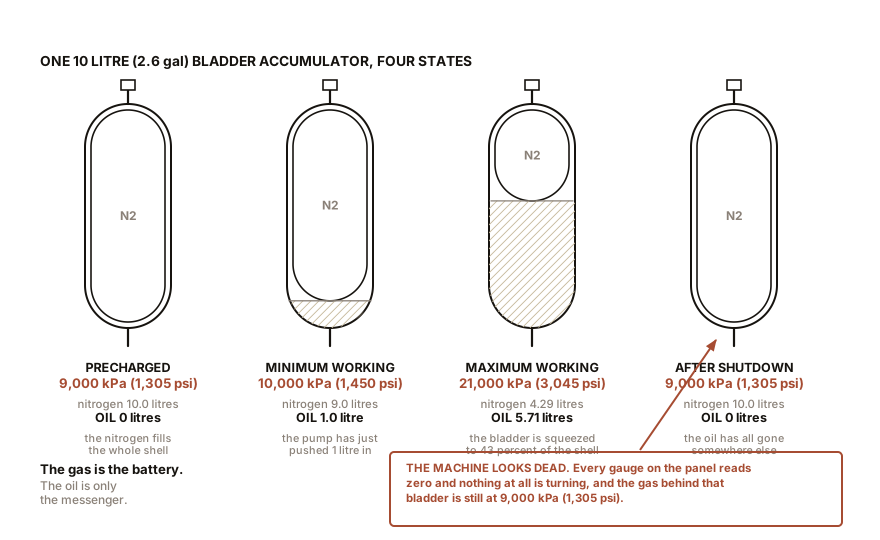
Precharge, P0. The nitrogen pressure with no oil in the accumulator at all. This is set once, with a nitrogen bottle and a charging rig, and it is the number stamped on the label.
Minimum working pressure, P1. The lowest system pressure at which you still want oil to come out.
Maximum working pressure, P2. Usually the relief valve setting.
The nitrogen obeys Boyle’s law, so the oil the accumulator can actually deliver is the difference between the gas volume at P1 and the gas volume at P2:
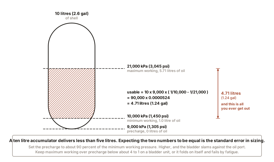
usable oil = V0 x ( P0 / P1 - P0 / P2 )Work a real one. A 10 litre (2.6 gal) bladder accumulator, precharged to 9,000 kPa (1,305 psi), in a system working between 10,000 kPa (1,450 psi) and 21,000 kPa (3,045 psi):
10 x ( 9,000/10,000  -  9,000/21,000 )
10 x ( 0.900  -  0.4286 )
=  4.71 litres  (1.24 gal)
Four and three quarter litres of oil, out of a ten litre vessel. That is normal: an accumulator’s nominal size is the shell, not the delivery, and expecting the two to be equal is a standard beginner’s error in sizing.
Two design rules that come out of the physics.
Set the precharge to about 90 percent of the minimum working pressure. Higher, and the bladder slams against the oil port when the system pressure falls, which destroys it. Lower, and you lose usable volume for nothing.
Keep the ratio of maximum working pressure to precharge below about 4 to 1 on a bladder unit. Beyond that the bladder is compressed so far that it folds on itself and fails by fatigue. A piston accumulator will happily take 10 to 1.
And why nitrogen, never anything else. Not air. Never oxygen. Hydraulic oil finely divided in a gas at high pressure and high temperature is a diesel engine’s fuel charge, and compressing oxygen into it produces exactly the result that description suggests. There are recorded accumulator explosions from air charging. Nitrogen is inert, cheap, and dry, and dryness matters too: water vapour in the gas side condenses and corrodes the shell from the inside where nobody looks.
Section 3: What an Accumulator Is Actually For
Five jobs, and only the first is the one people expect.
Peak flow supply, which is the big money. Consider a press that needs 60 litres/min (16 gal/min) for two seconds, then sits idle for eighteen. Its average demand is 6 litres/min (1.6 gal/min).
Without an accumulator, the pump must supply the peak: 60 litres/min
at 21,000 kPa (3,045 psi) needs 210 x 60 / 600 = 21 kW of
fluid power, so about a 26 kW (35 hp) motor, and for eighteen seconds
out of every twenty it is doing nothing but making heat.
With an accumulator, the pump supplies the average. A 10 litres/min (2.6 gal/min) pump needs 3.5 kW of fluid power, so a 5.5 kW (7.4 hp) motor, and the accumulator covers the two-second gulp. The press needs 2 litres (0.53 gal) in that two seconds, the pump provides 0.33 litres of it, and the accumulator provides the other 1.67 litres out of its 4.71 available. A motor a fifth the size, doing the same job. That is why accumulators are on presses, injection moulders, and anything with a duty cycle.
Emergency power. Pressure remains available when the pump has stopped. Every car with an electro-hydraulic brake system has a small brake accumulator to give you several assisted stops after the pump fails. Aircraft have them for landing gear and brakes.
Leakage make-up. A clamp that must hold for an hour can be held by an accumulator with the pump switched off, topping up the slow internal leakage.
Shock and pulsation damping. Chapter 21 covers water hammer; an accumulator on a line is a soft spot that absorbs the spike. A small diaphragm unit next to a piston pump smooths its ripple.
And shock absorption in suspension. A hydro-pneumatic suspension strut is an accumulator doing structural work, which is what makes those cars ride the way they do.
Section 4: The Hazard, Stated Properly
An accumulator holds full system pressure after the machine is switched off, the key is out, and every gauge on the panel reads zero.
That sentence has killed people, and the mechanism is always the same. A machine has stopped. There is no noise, no power, nothing turning. Somebody undoes a fitting or a cover, and 4.71 litres (1.24 gal) of oil at up to 21,000 kPa (3,045 psi) comes out through the gap, driving whatever was in front of it. The energy in that gas charge, computed as the isothermal work it can do expanding from the maximum working pressure back to the minimum, is around 67 kJ. For comparison, a 9 mm pistol bullet leaves the barrel with about 0.5 kJ.
The rules, and they are not negotiable.
Every accumulator circuit must have a means of discharge, and on well-built machines it is a manual bleed valve mounted on or beside the accumulator, sometimes wired so that switching the machine off opens it automatically. Find it before you need it.
Verify the discharge; do not assume it. A gauge on the accumulator side, not on the pump side, and read it. A machine’s main pressure gauge sits downstream of a check valve on many circuits and will read zero while the accumulator is fully charged behind it. The gauge you are looking at may be measuring the wrong side of the very component you are worried about.
Assume a stored charge on any unfamiliar machine. If you cannot find a discharge valve and a gauge that proves the state, treat the whole circuit as live.
Never attempt to discharge the gas side by undoing the gas valve. The gas valve is on the top and it is not a bleed screw. Discharging the gas correctly requires the proper charging rig.
And never weld, cut, drill or hot-work an accumulator shell, charged or not, which is worth saying because they are the right size to be tempting as a piece of scrap pipe.
IN PLAIN ENGLISH: An accumulator is a bottle of squeezed nitrogen with oil pressed up against it. The nitrogen does not care that you switched the machine off; it is still squeezed, and it will still push everything the oil can reach. This is the one component in a hydraulic system that is dangerous when the machine is dead, and it is dangerous precisely because everything else has gone quiet.
Section 5: The Air Side, Where the Store Is the Whole Point
Air stores energy well, so a pneumatic system’s receiver is not an accessory. It is the reason the system works the way it does.
Four jobs, and the receiver does all of them at once. It supplies peaks that exceed the compressor’s output. It lets the compressor run in long cycles rather than modulating, which is what a piston machine needs. It damps the compressor’s pulsation. And, from Chapter 9, it is the cheapest dryer you own, because air slows and cools in it and the water falls out.
Sizing. The traditional rule for a reciprocating compressor is a receiver volume in US gallons of roughly three to four times the compressor’s free air delivery in cfm, so a 10 cfm machine wants 30 to 40 gallons, which is 115 to 150 litres (30 to 40 gal). What that rule is really doing is limiting how often the compressor starts, because motor starts are what wears it out.
The useful calculation is draw-down. A 200 litre (53 gal) receiver holding air between 900 and 700 kPa (130 and 102 psi) gauge contains, expressed as free air:
200 litres x ( 200 kPa / 101 kPa ) = 396 litres of free air (105 gal)Feed a tool needing 300 litres/min, which is 79 gal/min or 10.6 cfm of free air, and the receiver alone will run it for:
396 / 300 = 1.32 minutes = 79 secondsSeventy-nine seconds of grinding before the compressor has to catch up. That number, and not the tank’s size in litres, is what determines whether a shop feels adequate or infuriating.
And now the hazard, which is the mirror image of the accumulator’s. That same 200 litre (53 gal) receiver at 900 kPa (130 psi) gauge holds, on an adiabatic expansion back to atmosphere, about 236 kJ, which is the energy of roughly 56 g (2.0 oz) of TNT. A hydraulic accumulator kills by driving a jet of oil. A receiver kills by becoming shrapnel, and it does so with no warning at all.
The failure mode is corrosion from the inside, which is invisible from the outside and is caused entirely by the water of Chapter 9 sitting in the bottom. So:
- Drain it. Daily, or fit an automatic drain. This is the single most effective thing anyone can do for the safety of a compressed air installation, and it costs nothing.
- Never repair a receiver by welding. A welded patch on a corroded pressure vessel is a bomb with a date on it.
- Do not defeat, adjust or replace the safety valve with anything other than the correct part. It is the receiver’s relief valve and it is the only thing standing between a stuck pressure switch and a burst tank.
- Respect the statutory inspection regime wherever you are. Pressure vessels are inspected on a schedule because the failure has no early symptoms.
ON THE BENCH: Measure the draw-down and the stored energy of your own compressor
Parts: your compressor; a stopwatch; any air tool that runs continuously, such as a blow gun held open or a die grinder; the tank volume from its sticker. Cost: nothing. Time: 20 minutes. Hazards: ear protection. Do not point a blow gun at anyone, at yourself, or at skin. Compressed air directed at a cut, or into any body opening, is lethal, and Chapter 21 says why in detail. Method: fill the tank to its cut-out pressure and switch the compressor off at the wall. Open the tool and time how long until the pressure falls to the point where the tool becomes useless, usually around 500 kPa (73 psi). What you should see: on a 50 litre (13 gal) tank running a die grinder, often under thirty seconds, which is why small compressors and continuous-duty tools are a poor match. Then compute the energy in the tank, and this is the part worth doing:
E in kJ = 2.5 x tank volume in litres x absolute pressure in MPa x 0.47For 50 litres at 900 kPa (130 psi) gauge, so 1.0 MPa absolute, that is about 59 kJ, which is 14 g (0.49 oz) of TNT. Now go and look at the tank you just calculated, and at its drain, and at whether the drain has ever been opened. That is the point of the exercise.
Section 6: Filtration, and Where the Filter Belongs
Chapter 9 established that contamination is the largest single cause of hydraulic failure and that the particles that matter are invisible. This section is about the four places a filter can go, and why the answer is not “all of them”.
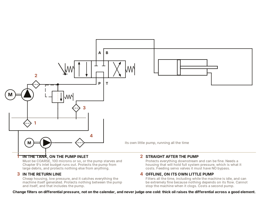
Suction strainer, in the tank on the pump’s inlet. Coarse only, 74 to 149 µm (0.003 to 0.006 in), because Chapter 10 says the inlet has only atmospheric pressure to work with and a fine filter there starves the pump into cavitation. Its job is to stop nuts, washers and rag, not dirt.
Pressure filter, immediately after the pump. Fine, 3 to 10 µm (0.0001 to 0.0004 in). It protects everything downstream, which is where the expensive and delicate parts are. The cost is a housing that must contain full system pressure, which is heavy and expensive.
Return filter, in the line back to tank. Fine, in a cheap low-pressure housing, which is why it is the commonest choice. It catches everything the system generated during the cycle. Its weakness is that it protects nothing between the pump and itself.
Off-line filtration, also called a kidney loop. A small dedicated pump and a very fine filter, running continuously on the reservoir, independent of the main circuit. It gives the best cleanliness of any arrangement, because it filters all the time including when the machine is idle, its flow rate is low so the filter can be extremely fine, and its failure does not stop the machine. This is standard on large installations and on anything with servo valves.
The measure of a filter is its beta ratio.
beta at x micrometres  =  particles above x upstream  /  particles above x downstream
efficiency  =  ( 1  -  1/beta )  x  100 percent
So a filter rated beta-10 equals 200 removes 199 out of every 200 particles of 10 µm (0.0004 in) and above, which is 99.5 percent. A filter rated beta-10 equals 2 removes half of them. Both may be sold as “10 micron filters”, and the beta figure is the one that means anything.
Two practical points that catch people.
Whether the filter has a bypass is a design decision, not a detail. A clogged filter with a bypass passes unfiltered oil; without one, it either starves the system or bursts its element. On a return filter, a bypass is right: unfiltered oil going to tank is better than a blown element sending the whole element’s contents into the system. On a pressure filter feeding servo valves, there must be no bypass, and instead there is a differential pressure indicator and a machine that gets shut down.
Change filters on differential pressure, not on the calendar, and never judge a filter cold. Cold thick oil raises the differential pressure across a perfectly good element, so the indicator on a machine that has just been started is telling you about Chapter 9’s viscosity curve rather than about the filter.
And the reservoir is part of the filtration system. Sized at three to five times the pump’s flow per minute, so the reference 10 litres/min (2.6 gal/min) pump gets a 30 to 50 litre (8 to 13 gal) tank. That size is not about capacity, it is about dwell time: oil must sit long enough for entrained air to rise out of it and for heat to be shed. A baffle separates the return from the suction so returning oil takes the long way round. The return line discharges below the oil surface, because oil splashing into air froths and Chapter 7 says what one percent of bubbles does. And the breather that lets the tank inhale as the oil level changes is itself a filter, and it is the most commonly neglected one on any machine.
Section 7: The FRL, Which Is the Pneumatic Equivalent
On the air side, conditioning is a standard three-piece assembly bolted to the wall at the point of use, and the order is fixed: Filter, Regulator, Lubricator.
Filter first, removing particulate and, in a coarse-separator design, liquid water by spinning the air. Standard element ratings are 5 to 40 µm (0.0002 to 0.0016 in) for general use and down to 0.01 µm for instrument air. It has a drain at the bottom and it needs to be opened, exactly like the receiver.
Regulator second, dropping the main’s pressure to whatever the tool or actuator needs. This is where most of the savings in a pneumatic shop are available, because air consumption rises steeply with pressure and most actuators are fed far more than they need. Chapter 17 puts numbers on that.
Lubricator last, injecting a fine mist of oil into the air stream to lubricate tool motors and cylinder seals. It is last for a reason: it must be downstream of the regulator, so that the oil delivery scales with the actual flow, and so that oil never gets into the regulator’s diaphragm.
And increasingly the lubricator is deliberately left out. Modern cylinders and valves come pre-lubricated for life with seals that do not need an oil mist, and an oil mist in the air is a contaminant: it coats the inside of the pipework, it ruins paint finishes, it is unacceptable near food or medicine, and it goes out of every exhaust port into the room. An FR set rather than an FRL is now the default on a new installation, and adding a lubricator to a system built without one contaminates the whole downstream network permanently, because the pipes retain it.
ON THE BENCH: Cut open a used oil filter
Parts: any used spin-on car oil filter, free from any garage’s waste bin; a tubing cutter, a hacksaw, or an oil filter cutting tool; gloves; a tray; a magnifier or a phone macro lens. Cost: nothing. Time: 30 minutes. Hazards: used oil is a skin irritant and a suspected carcinogen, so wear nitrile gloves and wash. Cut edges on a filter can are sharp. Do it outdoors over a tray. Method: cut round the base plate and lift the element out. Unroll the pleated media. What you should find, and all four are worth seeing: 1. The pleats, and how much area is folded into a can that size. Typically 0.5 to 1 m² (5 to 11 ft²) of media inside something the size of a mug, which is the same fin-area argument as a radiator. 2. The anti-drainback valve, a rubber diaphragm on the inlet holes, which stops the filter emptying back into the sump when the engine stops. 3. The bypass valve, usually a spring and disc in the centre tube, set to open at 100 to 200 kPa (15 to 29 psi) of differential. Find it, and hold it in your hand, because it is the decision described above made physical. 4. The debris. Wipe the outside of the media with a white cloth. On a filter off a high-mileage engine you will see grey metallic film. Put a magnet against it: if it clings, it is iron from the engine’s own wear. Why this is in a fluid power book: the geometry, the beta-ratio question, the bypass decision and the dirt are all identical to a hydraulic filter, and a hydraulic filter costs forty dollars while this one is free.
SLOW DOWN. Check Your Understanding: A machine has a 10 litre (2.6 gal) accumulator precharged to 9,000 kPa (1,305 psi) and works between 10,000 and 21,000 kPa (1,450 and 3,045 psi), delivering 4.71 litres (1.24 gal) of oil per cycle. Over a year it slowly loses nitrogen through the bladder, and the precharge drifts down to 5,000 kPa (725 psi). Nobody notices, because the machine’s pressure gauges still read the same. What has changed, and what will fail first? Answer before reading on.
The usable volume has almost halved, to
10 x (5,000/10,000 - 5,000/21,000) = 10 x (0.500 - 0.238) = 2.62 litres (0.69 gal). So the press that needed 1.67 litres per gulp still gets it, just, and the machine keeps working, which is exactly why nobody notices.What fails is the bladder, and it fails from the other end. As the system pressure falls at the bottom of each cycle toward 10,000 kPa (1,450 psi), the gas at only 5,000 kPa (725 psi) precharge cannot push all the oil out, so the bladder never fully re-expands and instead the accumulator empties completely of gas pressure relative to the oil port and the bladder is driven hard against the poppet at the bottom on every single cycle. Rubber slammed against a steel port a few thousand times a day tears. And when the bladder tears, the nitrogen goes into the oil, which then behaves like Chapter 7’s one percent of bubbles: the whole system goes spongy, the pump cavitates on aerated oil, and the fault presents as a pump problem.
The general lesson: an accumulator’s precharge is a service item with no symptom until it is a different component’s failure. It takes five minutes and a gauge to check, it is the cheapest preventive check in hydraulics, and it is almost never done.
The hardware is complete: something to make the flow, something to spend it, something to steer it, and something to store and clean it. What remains is to read it. The next two chapters teach the symbol language and then use it on circuits that solve real problems.

Bench Degree
Get the degree without the diploma.
Learn the material, not how to pass the exam.