Bench Degree·FLUID POWERchapter

Chapter 12: Controlling It: Valves
Three families, and the field’s own vocabulary muddles them. One decides where the fluid goes, one decides the maximum pressure, and one decides the rate. Sort those three and a hydraulic circuit stops being a thicket.
There are a great many valves and only three questions.
Where does the fluid go? That is a directional valve.
How high is the pressure allowed to get? That is a pressure valve.
How fast does the fluid move? That is a flow valve, and by Chapter 6 you know that this means it sets the actuator’s speed.
Every valve in fluid power is answering one of those three, and the reason the subject looks complicated is that manufacturers name valves after their application rather than their function. A counterbalance valve, a sequence valve and a relief valve are all the same device with the same insides, plumbed differently and given three names. Once you know that, the catalogue shrinks by two thirds.
Section 1: Directional Valves
The notation first, because it is universal and it is not obvious. A valve is described as ports slash positions. A 4/3 valve has four ports and three positions. A 3/2 has three ports and two positions. A 2/2 is a simple on-off tap.
The standard workhorse of hydraulics is the 4/3 spool valve. Four ports:
- P for pressure, from the pump.
- T for tank, the return.
- A and B, the two ports going to the two ends of the cylinder.
And the spool is the whole mechanism. It is a hardened steel rod with fat sections called lands and thin sections between them, sliding in a bore that has annular grooves cut into it, one per port. Slide the spool one way and the lands uncover a path from P to A and from B to T, so the cylinder extends. Slide it the other way and you get P to B and A to T, so it retracts. Put it in the middle and you get whichever of several possible arrangements the designer chose.
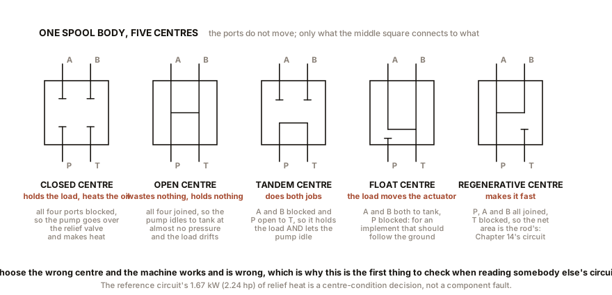
That middle arrangement is called the centre condition and it matters more than anything else about the valve. Five common ones:
Closed centre. All four ports blocked. The cylinder is trapped and holds position, and the pump has nowhere to go, so its full flow goes over the relief valve at full pressure. Excellent load holding, terrible heat. Correct with a variable displacement pump, which simply destrokes.
Open centre. All four ports connected together. The pump circulates freely to tank at almost no pressure, so almost no heat. But the cylinder is connected to tank at both ends, so it holds nothing at all and any load on it drifts down.
Tandem centre. P connected to T, A and B blocked. This is usually the right answer with a fixed pump: the pump is unloaded to tank so there is no heat, and the cylinder is trapped so the load holds. It is the commonest centre on mobile equipment.
Float centre. A and B both connected to T, P blocked. The actuator is free to be moved by hand or by the load, which is what you want on a machine where an implement should follow the ground.
Regenerative centre. P, A and B all joined together, T blocked. Used for the fast-approach trick of Chapter 11 Section 3.
Choose the wrong centre and the machine works and is wrong, which is why this is the first thing to check when reading somebody else’s circuit.
How the spool gets moved. By a hand lever, which is what a tractor’s spool block and a log splitter have. By a solenoid, an electromagnet, which is what factory automation uses. By a cam or roller, tripped by the machine’s own motion. By air pilot, common in pneumatics. Or by hydraulic pilot, which needs its own paragraph.
Why big valves are pilot operated. A solenoid that will fit on a valve body produces perhaps 50 to 100 N of force. The spool it has to move is subject to friction, spring load, and flow forces: fast-moving oil crossing a spool land pushes on it, and at 200 litres/min (53 gal/min) that push runs to several hundred newtons. So above roughly 60 to 80 litres/min (16 to 21 gal/min) the solenoid cannot win.
The answer is two valves. A small solenoid valve, which the solenoid can easily move, directs pressurised oil onto the ends of the big spool, and the oil moves it. The big valve is now hydraulically powered and electrically commanded. The cost is that a pilot-operated valve needs a minimum pilot pressure to work at all, typically 500 to 1,000 kPa (73 to 145 psi), which means it will not shift when the system is unloaded. Wiring one into a circuit whose centre condition dumps the pump to tank at zero pressure produces a machine that does nothing and has no fault in it, and this is a genuinely common commissioning error. The fix is either an internal pilot with a back-pressure valve in the tank line, or an external pilot supply.
Section 2: Pressure Valves
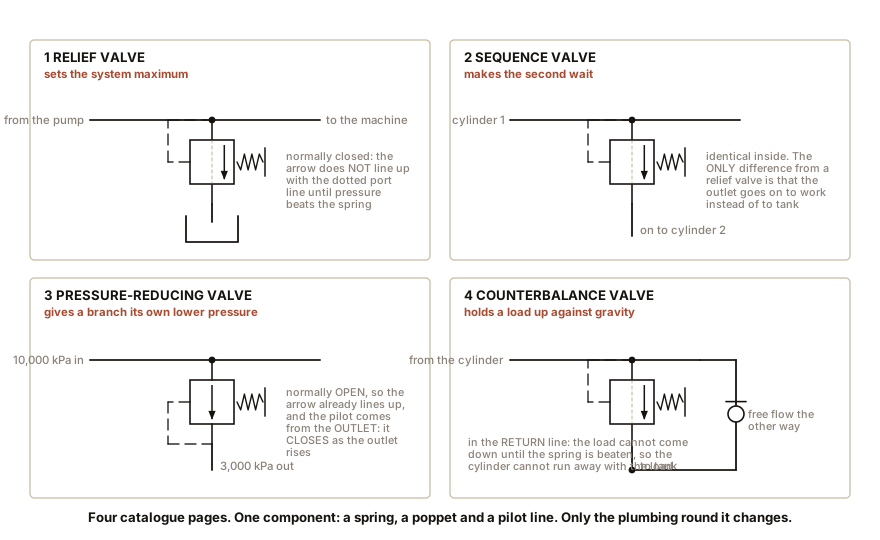
All of them are the same idea: a spring pushing a poppet or a spool shut, and fluid pressure trying to push it open. Adjust the spring and you adjust the pressure at which it opens. What changes between the types is what the valve is connected to.
The relief valve sits across the pump outlet and the tank, and it is the single component that defines the system’s maximum pressure. Chapter 10 explained why: a positive displacement pump has no pressure limit of its own.
A direct-acting relief valve is a spring and a poppet, and it has a characteristic worth knowing: pressure override. The valve cracks open at its set pressure and passes only a trickle. To pass the pump’s full flow the poppet has to open further, which compresses the spring further, which needs more pressure. So the pressure at full flow is 10 to 20 percent above the cracking pressure, and a “10,000 kPa relief” may actually be sitting at 11,500 kPa (1,670 psi) when it is dumping everything.
A pilot-operated relief valve fixes this with a two-stage arrangement: a small pilot poppet senses the pressure and controls a large main spool, so the main spool can open wide without much extra pressure. Override falls to about 5 percent, and the valve is also much quieter. This is what you find on any machine where the pressure setting actually matters.
The pressure-reducing valve provides a lower pressure to a branch of the circuit. It is normally open and closes as its outlet pressure reaches the setting. Used for a clamp that must not crush the workpiece while the rest of the machine runs at full pressure. And it is a heat generator, for Chapter 3’s and Chapter 8’s reason: the pressure it removes becomes heat, at a rate of pressure drop times flow.
The sequence valve is a relief valve plumbed in series rather than across the line: it stays closed, blocking the flow onward, until the pressure upstream reaches its setting, and then it opens and lets the flow continue to a second actuator. So the second thing happens only after the first thing has finished pushing. A clamp-then-cut circuit is two cylinders and one sequence valve, with no electrical controls at all, and it cannot get the order wrong.
The counterbalance valve is the same device again, plumbed into the return line of a cylinder carrying a suspended load. It holds a back pressure that supports the load’s weight, so the load cannot run away downward. This is Chapter 6’s runaway-load problem solved with one spring.
The unloading valve dumps the pump’s flow to tank at near-zero pressure when a remote pilot signal tells it the system does not need flow. It is the cheap way to fix Chapter 8’s idling heat problem on a fixed-displacement machine.
And the check valve, the simplest valve of all: a ball or poppet on a light spring that permits flow one way and blocks it the other. It appears everywhere, and its clever relative, the pilot-operated check valve, is Chapter 15’s star.
IN PLAIN ENGLISH: Every pressure valve is a spring holding a door shut against the fluid. Set the spring stiff and the door opens at a high pressure; set it soft and it opens at a low one. Everything else is a question of what is on each side of the door. Across the pump, it is a safety limit. In series, it makes one thing wait for another. In a return line, it holds a load up. One spring, four jobs, four names in the catalogue.
ON THE BENCH: You already own a direct-acting relief valve
Parts: a pressure cooker with a weighted vent, the traditional kind with a removable jiggler weight rather than a spring-loaded modern one; kitchen scales that read to a gram; a vernier or a drill bit set to measure the vent hole. Cost: nothing. Time: 20 minutes, plus cooking something. Hazards: steam burns badly and it burns before you feel it. Do the measuring cold. Watch the cooker in use from a distance and do not put a hand near the vent. Method: with the cooker cold, weigh the vent weight and measure the diameter of the hole it sits on. Then compute the pressure it will hold, and compare that with the pressure printed on the cooker. The arithmetic: a 3 mm (0.12 in) vent hole has an area of 7.07 mm² (0.011 in²). A weight of 72 g (2.5 oz) exerts 0.71 N. So:
P = 0.71 N / 7.07 mm2 = 0.10 MPa = 100 kPa (14.5 psi)What you should see: a figure close to the cooker’s rated 100 kPa (14.5 psi) gauge, which is the standard for a domestic pressure cooker. The weight of a small coin, sitting on a hole the size of a pencil lead, is regulating a pressure vessel, and the entire mechanism is Chapter 5’s equation. Then watch the override. Turn the heat up and the weight lifts and jiggles harder, and the pressure inside is now slightly above the setting, because a weight sitting flat holds one pressure and a weight being held up in a stream of steam holds a little more. That is pressure override, on your stove, and it is the same effect that makes a hydraulic relief valve read high at full flow. A spring-loaded cooker valve shows it more strongly than a weighted one, which is why the weighted kind is the more accurate regulator.
Section 3: Flow Valves, and the Square Root That Surprises People
A flow valve is a hole. That is genuinely all it is, and the sophistication is entirely in what is done around the hole.
The flow through an orifice is:
Q = Cd x A x square root of ( 2 x pressure drop / density )with Cd, the discharge coefficient, being about 0.62 for a sharp-edged hole and up to 0.9 for a well-shaped nozzle.
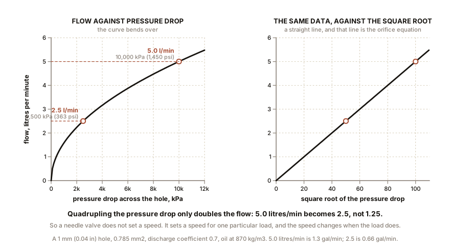
The important part is the square root. Flow through a fixed hole is not proportional to the pressure drop across it. It is proportional to the square root. Which means:
Four times the pressure drop gives twice the flow.
Work one: a 1 mm (0.04 in) diameter hole, 0.785 mm² (0.0012 in²), with 10,000 kPa (1,450 psi) across it, in oil of 870 kg per cubic metre:
velocity  =  square root of ( 2 x 10,000,000 / 870 )  =  152 m/s   (499 ft/s)
Q         =  0.62 x 0.000000785 x 152  =  0.0000740 m3/s  =  4.4 litres/min  (1.16 gal/min)
Now drop the pressure across it to 2,500 kPa (363 psi), a quarter, because the load got heavier and the cylinder now needs more of the available pressure. The flow halves to 2.2 litres/min (0.58 gal/min).
Which means a plain needle valve does not set a speed. It sets a speed for one particular load. Change the load and the actuator’s speed changes, and this is the single most annoying property of cheap flow control and the reason machines drift out of adjustment.
The fix is the pressure-compensated flow control valve. It contains two elements in series: the adjustable orifice you set, and a compensator spool that automatically throttles to hold a constant pressure drop across that orifice, usually around 700 kPa (102 psi), no matter what the load downstream is doing. Constant drop across a fixed hole means constant flow, so the speed becomes load-independent. It costs perhaps three times a needle valve and it is worth it on anything that has to be repeatable.
Flow dividers are the same idea used to split one pump’s flow between two actuators in a fixed ratio, which is Chapter 6’s shared-pump problem addressed with hardware.
ON THE BENCH: Confirm the square root law with a hose
Parts: garden tap, hose, hose-bib pressure gauge, an adjustable nozzle or a gate valve, a 10 litres (2.6 gal) bucket, a stopwatch. Cost: nothing beyond the gauge from Chapter 3. Time: 30 minutes. Hazards: none. Method: fit the gauge upstream of the nozzle. Set the nozzle to a fixed opening and do not touch it again for the rest of the experiment. Now vary the supply pressure by partly closing the tap, and at each setting record the gauge reading and the time to fill the bucket. Take four readings, aiming for pressures roughly at 400, 300, 200 and 100 kPa (58, 44, 29 and 15 psi). What you should see: the flow falls as the square root. From 400 kPa to 100 kPa, a factor of four in pressure, the flow should fall by a factor of two, not four. So if the bucket filled in 30 seconds at 400 kPa (58 psi), expect about 60 seconds at 100 kPa (15 psi), and about 42 seconds at 200 kPa (29 psi). Plot it on graph paper, flow against pressure. You will get a curve that bends over, and if you plot flow against the square root of pressure you will get a straight line. That straight line is the orifice equation, measured in a garden with a bucket. The lesson for real machines: every needle valve, every restrictor, every partly-open spool and every nozzle in the world obeys that curve. It is why an actuator’s speed changes when the load changes, and why pressure-compensated valves exist.
Section 4: Proportional and Servo Valves, and Where the Money Goes
Everything so far has been a valve with positions: open, shut, or one of three. A proportional valve has no positions. Its spool is moved a continuously variable amount by a solenoid whose force is proportional to the current through it, so the valve’s opening, and therefore the flow, follows an electrical signal.
A proportional valve is the industrial workhorse. Bandwidth, meaning how fast it can be told to change, is roughly 10 to 50 Hz. It has some hysteresis and some deadband around centre, it is reasonably tolerant of ordinary oil, and it costs hundreds rather than thousands. This is what moves an excavator’s boom under an electronic control, an injection moulding machine’s screw, and a mobile crane’s winch.
A servo valve is the precision instrument. A tiny torque motor moves a flapper between two nozzles, creating a pressure difference that moves the main spool, and the spool’s actual position is fed back either mechanically through a feedback wire or electrically through a position transducer. Bandwidth 100 to 300 Hz, hysteresis under one percent, near-zero deadband.
And here is where the money goes, because it is instructive. The spool-to-bore clearance in a servo valve is 1 to 3 µm (0.00004 to 0.00012 in), and the spool and bore are lapped as a matched pair, so they are not interchangeable and cannot be repaired by substitution. The internal orifices in the pilot stage are a few tenths of a millimetre. Consequently:
- It demands very clean oil. An ISO 4406 code of 16/14/11 or better, and Chapter 9 says why: a particle of 5 µm (0.0002 in) in a clearance of 2 µm (0.00008 in) is not a contaminant, it is a wedge.
- A single particle can silence the machine, by jamming the pilot stage, and the fault looks electrical.
- It costs several thousand, essentially all of it in the lapping and the cleanliness.
The honest engineering position is that most machines should not use a servo valve. Ask what bandwidth the job needs. A press platen, a crane winch, a steering ram and an excavator boom are all well served at 10 Hz. Flight control surfaces, engine test rigs, active vibration control and materials testing machines genuinely need 100 Hz and more. Specifying a servo valve where a proportional valve would do buys a maintenance liability and no performance.
ON THE BENCH: Take a spool valve apart
Parts: a scrap hydraulic spool valve. A single-spool tractor or log-splitter valve is about $40 new and is often free from a scrapyard, a farm workshop or a plant hire company’s scrap pile; sockets; a tray; degreaser. Cost: nothing to about $40. Time: an hour. Hazards: some spool valve bodies contain a relief cartridge with a stiff spring behind a circlip. Undo it with the body clamped and your face out of line. Old oil on skin and floor. Method: remove the end covers and slide the spool out. Wipe it clean and hold it up to the light. What you should find, and look for all four: 1. The lands, and how little overlap there is between a land and its groove. A few tenths of a millimetre of overlap is what holds thousands of kilopascals. 2. The metering notches, small triangular or V-shaped grooves cut into the leading edges of the lands. These are the reason a hand lever gives fine control: as the spool starts to move, the notch opens gradually rather than the whole land clearing at once, so the flow ramps up with lever travel instead of arriving all at once. That is a proportional valve made out of geometry rather than electronics, for a fortieth of the price, and it is the single most elegant detail on a cheap valve. 3. The centre condition. With the spool at rest in the middle, work out from the land positions which ports are connected. Then say which of the five in Section 1 it is, and therefore what the machine it came off does when the operator lets go. 4. The wear. Hold the spool at a shallow angle to a light. Scoring runs along the direction of sliding, and it is caused by particles, not by pressure. What to take away: roll the spool in your fingers. This is the entire control system of a machine that can lift a tonne, and it is a lump of steel with grooves in it.
SLOW DOWN. Check Your Understanding: A machine has a fixed-displacement pump, a relief valve set to 15,000 kPa (2,175 psi), and a 4/3 hand valve with a closed centre. The operator complains that the oil overheats after twenty minutes even though he is only using the machine occasionally. The obvious diagnosis is a fault. There is no fault. What is happening, and which single component would you change? Answer before reading on.
The closed centre is doing exactly what a closed centre does. With the lever released, all four ports are blocked, so the pump’s entire flow has nowhere to go except over the relief valve at 15,000 kPa (2,175 psi). If the pump makes 20 litres/min (5.3 gal/min) that is
150 x 20 / 600 = 5 kWgoing into the oil continuously, whenever the operator’s hand is off the lever, which on an occasionally used machine is most of the day. Chapter 8’s arithmetic says a 40 litres (11 gal) reservoir will climb about 4.5 degrees Celsius a minute, so twenty minutes is 90 degrees of rise and the machine is cooking.Change the valve for one with a tandem centre, which connects P to T so the pump circulates at near-zero pressure while still blocking A and B so the load holds. Same pump, same relief, same lever, and the idling heat falls by a factor of thirty or more.
And the general lesson, which is the one to keep: in fluid power, the heat is almost never caused by the component that gets hot. The oil in the tank is hot because of a decision made in a valve two metres away, and diagnosing by temperature alone will send you to the wrong place every time. Follow the flow and ask where the pressure is falling without moving anything.
Valves decide where and how much. The next chapter deals with the two components that decide when: a store of energy that can supply more power than the pump can, and the filtration and conditioning that decides whether any of it lasts.

Bench Degree
Get the degree without the diploma.
Learn the material, not how to pass the exam.