Bench Degree·FLUID POWERchapter

Chapter 11: Doing Work
A cylinder is stronger going out than coming back, and faster coming back than going out, and the two ratios are the same number. This chapter is about why, and about what happens when the thing you want is a rotation instead of a push.
An actuator is where the fluid stops being a means and becomes an end. There are three kinds and you have met all three without noticing: a cylinder gives a straight push, a rotary actuator gives a limited turn, and a motor gives continuous rotation.
This chapter takes them in that order, and spends most of its length on the first one, because the cylinder holds the most useful surprise in the subject.
Section 1: What a Cylinder Is Made Of
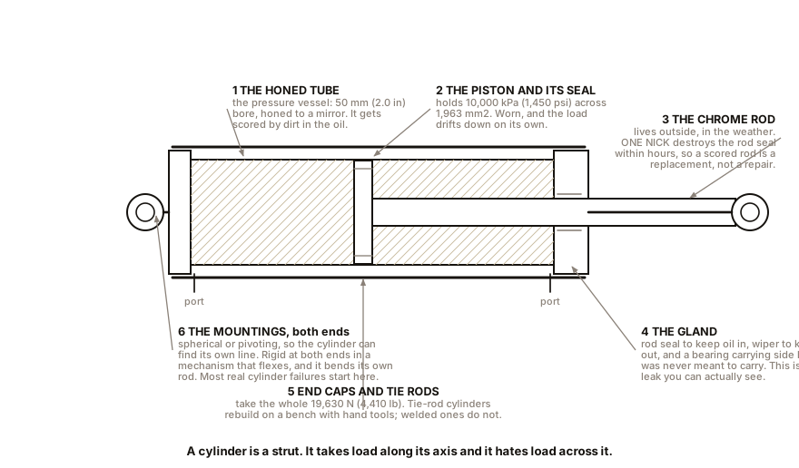
Six parts, and each of them is a place things go wrong.
The tube, which is the pressure vessel and is honed smooth on the inside so the piston seal has a surface to work against.
The piston, carrying a seal on its outside diameter and often a bearing ring to keep it from touching the tube.
The rod, which is hard chrome plated, both for wear and because it lives outside the machine in the weather. A nicked rod destroys the rod seal within hours, which is why a scored rod is a replacement rather than a repair, and why guarding a rod against falling debris is worth more than any seal upgrade.
The gland, at the rod end, holding a rod seal to keep oil in, a wiper or scraper to keep dirt out, and a bearing to carry side load.
The end caps, which take the whole force and are either bolted on through tie rods, welded, or screwed. Tie-rod cylinders can be rebuilt on a bench with hand tools; welded ones generally cannot.
And the mounting, which is where most cylinder failures actually originate. A cylinder is a strut: it takes load along its axis and it hates load across it. A cylinder mounted on rigid brackets at both ends in a mechanism that flexes will bend its own rod, so most real installations use spherical or pivoting mounts at both ends so the cylinder can find its own line.
The types, briefly. A single-acting cylinder is pressurised on one side only and returned by a spring or by the load’s own weight, which is what a bottle jack and a tipper body are. A double-acting cylinder has a port at each end and is driven both ways, which is nearly everything else. A double-rod cylinder has a rod out of both ends, which makes it symmetrical, and Section 3 explains why anybody would want that. A telescopic cylinder nests several stages to get a long stroke out of a short body, which is what a tipper lorry and a crane boom use.
Section 2: The Differential Area Problem
Here is the thing that surprises everyone.
Take the reference cylinder: 50 mm (2.0 in) bore, 25 mm (1.0 in) rod, 400 mm (16 in) stroke, running at 10,000 kPa (1,450 psi) with 10 litres/min (2.6 gal/min).
Extending, the pressure acts on the whole piston face:
area  =  0.7854 x 50 x 50  =  1,963 mm2   (3.04 in2)
force =  10 MPa x 1,963    =  19,630 N     (4,410 lb)
speed = 10 x 16,667 / 1,963 = 85 mm/s (3.3 inches per second)Retracting, the pressure acts on the piston’s other face, and that face has the rod attached to the middle of it. The rod’s cross-section is not available to push on. So:
rod area  =  0.7854 x 25 x 25  =  491 mm2   (0.76 in2)
effective area  =  1,963 - 491  =  1,472 mm2   (2.28 in2)
force  =  10 MPa x 1,472        =  14,720 N     (3,310 lb)
speed  =  10 x 16,667 / 1,472   =  113 mm/s     (4.5 inches per second)
Same cylinder, same pressure, same flow. Twenty-five percent less force coming back and thirty-three percent more speed.
The ratio is 1,963 divided by 1,472, which is 1.33, and it appears in both directions: force divides by it, speed multiplies by it. It has to, because the power is the same both ways, and power is force times speed.
Where it bites in practice, and it bites often:
Sizing. A cylinder sized on its extend force will be a quarter weaker on the return. If the job’s hard direction is the retract, that is the direction to size for, and people forget.
Timing. A cylinder does not take the same time each way, so any circuit that assumes symmetry, or any operator who has learned the extend timing, gets a surprise on the return.
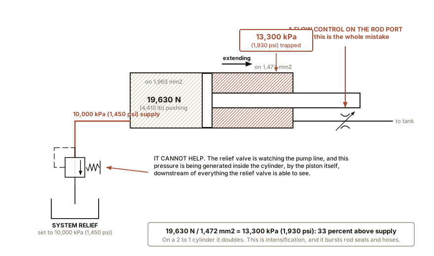
And the trap that catches designers: a retracting cylinder can generate more pressure than the system supply. Consider a cylinder retracting under pressure with its extend port blocked, perhaps by a slow flow control or a closed valve. The 1,472 mm² (2.28 in²) annulus is pressurised at 10,000 kPa (1,450 psi), generating 14,720 N, and that force is now acting on the 1,963 mm² (3.04 in²) full-bore side, which is trying to push oil out through the restriction. The pressure on the blocked side becomes:
14,720 N / 1,963 mm2 = 7.5 MPaWhich is lower, and that direction is safe. Now do it the other way, which is the dangerous one: extend the cylinder with the annulus side restricted. The full-bore side pushes with 19,630 N, or 4,410 lb, and that force acting on the 1,472 mm² (2.28 in²) annulus gives:
19,630 / 1,472 = 13.3 MPa = 13,300 kPa (1,930 psi)Thirty-three percent above system pressure, on the rod side, from nothing more sinister than a flow control valve on the wrong port. This is called intensification, it is real, it bursts rod seals and hoses, and it is the reason Chapter 15 is careful about which port you meter. On a cylinder with a fat rod the effect is much bigger: a 2 to 1 ratio cylinder, where the rod area is half the piston area, doubles the pressure.
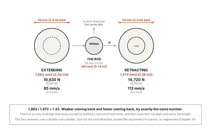
IN PLAIN ENGLISH: A cylinder’s piston is a disc with a rod stuck to one side of it. Push on the plain side and the fluid gets the whole disc. Push on the other side and the fluid gets the disc minus the circle where the rod is bolted on, because the rod is in the way. Less area, so less force. And less space to fill, so the same amount of fluid fills it faster. The rod is the reason the cylinder is not symmetrical, and there is no way to design that away except by putting a rod out of both ends.
ON THE BENCH: Measure both directions on one cylinder
Parts: a small double-acting pneumatic cylinder, 25 or 32 mm (1.0 or 1.25 in) bore, about $20 new online and often free from a machine shop’s scrap bin; a compressor with a regulator and gauge; kitchen or bathroom scales; a length of angle iron or a workbench edge to react against; two lengths of 6 mm (0.24 in) air hose; a hand valve or a three-way tap. Cost: about $25 if you own a compressor. Time: an hour. Hazards: stay at or below 400 kPa (58 psi) for this and secure the cylinder before pressurising it. An unrestrained cylinder given air on one port becomes a small ram that moves fast. Keep fingers away from the rod end and from any pinch point. Wear eye protection: a hose of 6 mm (0.24 in) bore that comes off a push-fit at 400 kPa (58 psi) whips. Method: clamp the cylinder so the rod pushes squarely down onto the scales. Set the regulator to exactly 400 kPa (58 psi) and note it. Extend the cylinder onto the scales and read the peak force. Then invert the arrangement so the cylinder pulls the scales, using a hook or a loop of strap, and read the retract force at the same 400 kPa (58 psi). The prediction, for a 25 mm bore with a 10 mm rod:
piston area 0.7854 x 25 x 25 = 491 mm2 (0.76 in2)rod area 0.7854 x 10 x 10 = 78.5 mm2 (0.122 in2)annulus 491 - 78.5 = 412 mm2 (0.64 in2)extend 0.4 MPa x 491 = 196 N, which the scales read as 20 kg (44 lb)retract 0.4 MPa x 412 = 165 N, which the scales read as 17 kg (37 lb)What you should see: the two readings differing by about 16 percent, in the direction predicted, and both perhaps 5 to 10 percent low because of seal friction. The ratio is what matters and it should be right to within a couple of percent, because friction affects both directions similarly and largely cancels out of a ratio. Then measure the speeds. Time the full stroke each way with the ports unrestricted. Retract should be faster by exactly the same 1.19, and confirming that a force ratio and a speed ratio are the same number is the most satisfying five minutes in this volume. If the retract force reads much lower than predicted: check the regulator has not sagged, because a small compressor’s regulator droops when flow is high, and the retract stroke moves faster and therefore demands more flow.
Section 3: Getting Around It
Four ways, each with a cost.
A double-rod cylinder. Rod out of both ends, equal areas, identical force and speed in both directions. Used where symmetry matters, on machine tool tables and in test rigs. The costs are length, two rod seals to leak, and two rods to protect.
Size for the hard direction. Cheapest and commonest. Accept the asymmetry and pick the bore that makes the difficult stroke work.
Use the asymmetry. A press that needs enormous force one way and only needs to return an empty tool the other way is the ideal application, which is why nearly all presses push on the full-bore side.
Or exploit it, with a regenerative circuit. Connect the rod-end port to the full-bore port so both sides see supply pressure at once. Now the net force is pressure times the rod area only, which is small, but the oil pushed out of the annulus joins the incoming supply, so the cylinder moves very fast on a modest pump. It is the standard trick for the rapid approach stroke of a press, and Chapter 15 draws the circuit. On a 2 to 1 ratio cylinder, regeneration exactly doubles the speed.
Section 4: The Limits of a Cylinder
Buckling. A cylinder in compression is a strut, and a long thin strut buckles at a load that falls as the square of its length. This is Euler’s problem and it is why cylinder manufacturers publish stroke-against-bore charts rather than leaving it to the buyer. The practical shape of it: a cylinder used near its full rated force at a long stroke needs a rod much fatter than the force alone would suggest, and doubling the stroke roughly quarters the buckling load. Long cylinders also use a stop tube, a spacer that stops the piston reaching the very end of its travel, which shortens the unsupported rod length at full extension where the buckling risk is worst.
Side load. The rod bearing in the gland is small and is not a structural bearing. Side load wears the gland oval, which leaks, and bends the rod, which destroys the seal. Fit the cylinder so it can swing.
Speed. A cylinder arriving at the end of its stroke has kinetic energy that has to go somewhere, and the somewhere is the end cap. A 50 kg (110 lb) load at 500 mm/s (20 inches per second) carries 6.3 J, which sounds small and is a hammer blow delivered thousands of times a day. So cylinders above modest speeds have cushions: the last 20 to 30 mm (0.8 to 1.2 in) of travel closes off the main port and forces the fluid out through an adjustable needle valve, decelerating the piston. A pneumatic cylinder cushions naturally, because trapping compressible air ahead of the piston is itself a spring, which is Chapter 7 being useful again. Hydraulic cushions have to be machined in.
ON THE BENCH: Work out a cylinder’s rod diameter without touching it
Parts: a stopwatch; a tape measure; any machine with a double-acting cylinder you can watch through its full stroke. A skip lorry, a tail lift, a tipper, a scissor lift, a log splitter or a garage two-post ramp. Cost: nothing. Time: 20 minutes. Hazards: stand clear, agree signals with whoever is operating it, and do all measuring with the machine shut down and the load on the ground. Never put a hand near a moving rod or a pinch point. Method: have the machine run one cylinder from fully retracted to fully extended at full lever, and time it. Then time the return. Repeat three times each way and take the fastest of each. Now invert Chapter 6’s speed equation. The same flow goes each way, so the times are inversely proportional to the areas:
piston area / annulus area = extend time / retract timeAnd since the annulus is the piston area minus the rod area:rod area = piston area x ( 1 - retract time / extend time )Worked, on a cylinder that extends in 6.0 s and retracts in 4.5 s: the ratio is 1.33, so the annulus is 75 percent of the piston, so the rod’s cross-section is 25 percent of the piston’s, so the rod’s diameter is the square root of 0.25, which is half the bore. What you should see: a ratio between about 1.1 and 2.0, and therefore a rod between about 30 and 70 percent of the bore, which is the range real cylinders are built in. Then measure the rod with the tape measure and check yourself. What you have done: determined a hidden internal dimension of a machine from two stopwatch readings, using nothing but the fact that the flow is the same in both directions. That is what it means to be able to think about these machines rather than look them up.
Section 5: Rotary Actuators and Motors
A rotary actuator turns through a limited angle, typically 90, 180 or 270 degrees, and comes in three constructions: a rack and pinion driven by one or two pistons, a vane type with a single vane sweeping a chamber, and a helical type where a piston’s axial travel drives a screw. Used on valve actuators, indexing tables, clamping and turning devices. Torque comes from the same place it always does: pressure times an area times a radius.
A hydraulic motor is a pump run backwards, and often the same casting sold with a different label. Feed it flow and it turns. The arithmetic is tidy:
torque in N-m   =  displacement in cm3/rev  x  pressure in bar  /  62.8
speed in rpm    =  flow in litres/min  x  1,000  /  displacement in cm3/rev
A motor of 100 cm³ per revolution (6.1 in³) at 200 bar, which is 20,000 kPa (2,900 psi), on 60 litres/min (16 gal/min):
torque  =  100 x 200 / 62.8  =  318 N-m   (235 lb-ft)
speed   =  60 x 1,000 / 100  =  600 rpm
power   =  200 x 60 / 600    =  20 kW     (27 hp)
Three hundred and eighteen newton-metres out of something the size of a grapefruit, and that power density is the real reason mobile machinery uses hydraulic motors for wheels and tracks rather than electric ones with gearboxes.
The families mirror the pumps. Gear motors are cheap and fast. Vane motors are quiet. Axial piston motors are efficient and can be variable displacement, so a machine can trade torque for speed on the move, which is the hydrostatic transmission in Chapter 19. Orbital or gerotor motors, often called low-speed high-torque, use an internal gear rolling round an external one to get a large displacement into a small body, and they turn slowly with a lot of torque, which suits a skid-steer’s wheel or an auger drive directly with no gearbox at all.
And air motors, which have one property no electric motor has.
An electric motor that is stalled draws its locked-rotor current, several times its rated current, and dissipates all of it in the windings, which are not moving and therefore not being cooled. A stalled electric motor is a heater with a thermal fuse in it and a few minutes to live.
A stalled air motor simply stops. No air flows, so no work is done, so nothing is dissipated, and it sits there at supply pressure indefinitely without getting warm. Worse for it, the expanding air inside an air motor is getting colder, which is Chapter 1 of the refrigeration volume of this series, so an air motor working hard often has frost on its exhaust.
That property, plus the fact that an air motor has no electrical spark anywhere on it, is why air motors and air tools are the standard in paint booths, grain handling, mines, refineries and anywhere else where the atmosphere might be flammable. The cost is efficiency: an air motor converts perhaps 10 to 20 percent of the electrical energy that went into the compressor, which is Chapter 17’s uncomfortable arithmetic.
SLOW DOWN. Check Your Understanding: A machine has a cylinder that must push 15,000 N, which is 1,530 kg or 3,372 lb, extending, and pull the same load retracting. A colleague sizes it on the extend stroke: at 10,000 kPa (1,450 psi) that needs 1,500 mm² (2.33 in²), so a 45 mm (1.77 in) bore. Is that cylinder going to work? If not, what is the smallest bore that will, and is there a cheaper answer than a bigger cylinder? Answer before reading on.
It will not retract. With a 45 mm bore and a typical 25 mm (1.0 in) rod, the annulus is 1,590 minus 491, which is 1,099 mm² (1.70 in²), and at 10,000 kPa that gives only 10,990 N (2,470 lb). The cylinder will extend against the load and then stop dead trying to come back, which on a real machine means a job half done and a puzzled operator.
Sizing on the retract stroke instead: at 10,000 kPa (1,450 psi) you need an annulus of 1,500 mm², so the piston area must be 1,500 plus the rod’s 491, which is 1,991 mm² (3.09 in²), giving a 50 mm (2.0 in) bore. Which is the reference cylinder, and it is the honest answer.
And now the cheaper answer, which is the point of the question. You are not obliged to use the same pressure in both directions. Raise the pressure on the retract stroke only, and the 45 mm cylinder does the job:
15,000 / 1,099 = 13.6 MPa, so 13,600 kPa (1,970 psi) on the return. That costs one pressure-reducing valve or a sequence valve, and Chapter 12 has both. Whether it is a good idea depends on the pump, the hoses and the rest of the circuit, and here is the honest trade: the 50 mm (2.0 in) cylinder is simpler and will still be simple when somebody else maintains it in 2040. Cleverness in a hydraulic circuit is a debt paid by whoever holds the spanner next, and knowing when not to be clever is part of the craft.
Force and speed exist and can be sent in a straight line or round in a circle. What decides where the fluid goes, and how much of it, is the valve, and the field’s own vocabulary for valves is muddled enough that the next chapter starts by sorting it out.

Bench Degree
Get the degree without the diploma.
Learn the material, not how to pass the exam.