Bench Degree·FLUID POWERchapter

Chapter 10: Making Pressure
Almost every machine in this book uses a pump that traps a fixed slug of fluid and carries it round. This chapter says why that choice is nearly universal, what the four kinds cost you, and how to find out what your own compressor really delivers.
There are two ways to move a fluid and fluid power uses one of them almost exclusively.
A dynamic machine flings fluid outward with a spinning impeller and lets its velocity turn into pressure. Your central heating pump, a fire pump, a jet engine’s compressor and the water pump in a car engine are all dynamic. They move enormous volumes cheaply and they are wonderful at it.
A positive displacement machine encloses a definite volume of fluid, seals it off, moves it from the inlet to the outlet, and releases it. Then it does it again. Your heart, a bicycle pump, a piston compressor and every hydraulic pump in this book are positive displacement.
The difference that decides it is what happens when you block the outlet.
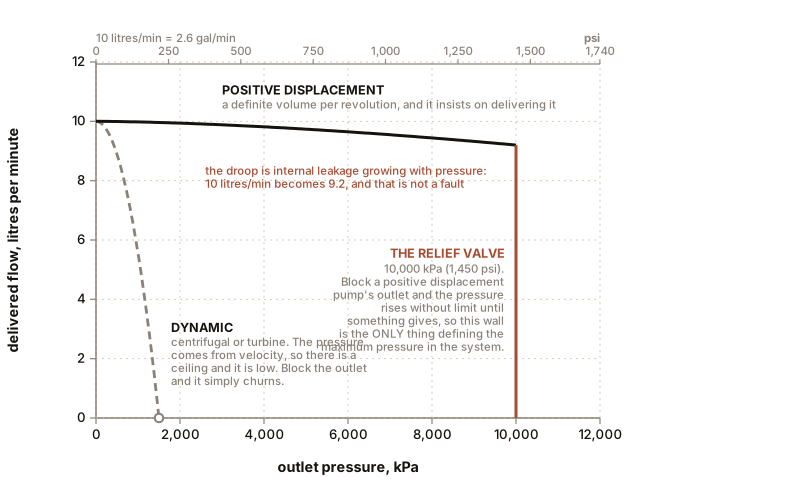
Block the outlet of a centrifugal pump and it churns. The impeller spins, the fluid spins with it, the pressure rises to whatever the tip speed can produce and stops there, and no more. That ceiling is set by velocity, and pressure rises as the square of it, so to reach a hydraulic 21,000 kPa (3,000 psi) with a centrifugal machine on oil you would need an impeller tip speed of roughly 220 m/s (720 ft/s), which is a machine the size of a car making a noise like a turbine.
Block the outlet of a positive displacement pump and the pressure rises without limit until something gives. The pump does not have an opinion about pressure. It has a volume per revolution and it insists on delivering it. That is why the relief valve of Chapter 6 is not an optional safety extra: it is the only thing defining the maximum pressure in the entire system, and a hydraulic power unit without one destroys itself in seconds.
Section 1: The Three Hydraulic Pumps
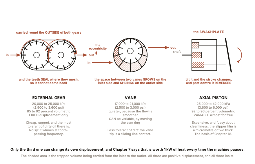
The gear pump. Two meshing gears in a close-fitting housing. Fluid is carried round in the spaces between the teeth from inlet to outlet, and the meshing teeth stop it coming back.
- Pressure: up to about 20,000 to 25,000 kPa (2,900 to 3,600 psi).
- Volumetric efficiency: 85 to 92 percent when new.
- Fixed displacement only. There is nothing to adjust; the gears are the size they are.
- Cheap, rugged and the most tolerant of dirty oil of any hydraulic pump, which is why it is on tractors, tail lifts, tipper bodies and log splitters.
- Noisy. Each tooth entering mesh produces a pressure pulse, so a gear pump whines at tooth-passing frequency, typically 1 to 2 kHz.
The vane pump. A slotted rotor spinning inside an oval or offset cam ring, with vanes that slide outward against the ring. The space between two vanes grows on the inlet side and shrinks on the outlet side.
- Pressure: 17,000 to 21,000 kPa (2,500 to 3,000 psi) for industrial types.
- Quieter than a gear pump, because the flow is smoother.
- Can be made variable displacement by moving the cam ring to change the eccentricity, and this is the classic industrial pressure-compensated pump.
- Less tolerant of contamination, because the vane tips are a sliding line contact under load.
The piston pump. A ring of small pistons in a rotating barrel, their ends riding on an inclined plate called a swashplate. As the barrel turns, each piston is pushed in and drawn out once per revolution, and the stroke length depends on the swashplate’s angle.
- Pressure: 25,000 to 42,000 kPa (3,600 to 6,000 psi) routinely, and radial piston designs reach 70,000 kPa (10,000 psi).
- Volumetric efficiency 92 to 96 percent.
- Variable displacement is nearly free, because tilting the swashplate changes the stroke and therefore the displacement, continuously, from full flow to zero. Tilt it past centre and the pump reverses, which is the whole basis of the hydrostatic transmission in Chapter 19.
- Expensive, and fussy about cleanliness, because the slipper-to-swashplate film is a micrometre or two thick.
Why variable displacement is the whole argument. Chapter 8 showed a circuit running at 12 percent efficiency because a fixed pump made 10 litres/min (2.6 gal/min) when the job wanted 4 litres/min (1.06 gal/min), and the surplus went over a relief valve as 1 kW of heat.
A pressure-compensated pump watches its own outlet pressure and reduces its displacement to hold that pressure at a set value. When the actuator stops, the pump destrokes to almost nothing: it delivers only the trickle needed to make up leakage, at full pressure, and consumes almost no power. The relief valve becomes what it should always have been, an emergency device that never operates.
A load-sensing pump goes further. It measures the pressure difference across the operator’s control valve and adjusts its displacement to keep that difference at a small constant value, typically 1,400 to 2,000 kPa (200 to 290 psi), called the margin pressure. The result is that the pump delivers exactly the flow the operator is asking for, at exactly the pressure the load needs, plus the margin. Every excavator built in the last thirty years works this way, and Chapter 16 explains what it feels like from the seat.
IN PLAIN ENGLISH: A fixed pump is a tap that is always fully open, so anything you do not want has to be spilled somewhere. A variable pump is a tap that turns itself down to exactly what you asked for. Both deliver the same fluid to the same job; only one of them heats the oil while doing it.
Section 2: What the Nameplate Does Not Say
Two honest numbers about pumps, both of which show up as complaints in the field.
Volumetric efficiency is not a constant. A gear pump quoted at 92 percent means 92 percent at a specific pressure, speed and oil viscosity. Raise the pressure and internal leakage past the gear tips rises with it, so the delivered flow falls. Warm the oil and it falls further, because thinner oil leaks more easily. A pump that delivers 10 litres/min cold at 5,000 kPa (725 psi) may deliver 8.5 litres/min hot at 20,000 kPa (2,900 psi), and neither figure is a fault.
And this is precisely how a worn pump announces itself. Wear opens the internal clearances, so leakage rises, so the flow falls, and it falls most at high pressure. A worn pump’s symptom is a machine that is normal when lightly loaded and slow when working hard. Chapter 21 gives the ten-minute test: measure the flow at low pressure and again at working pressure, and compare the drop against the manufacturer’s figure.
Section 3: Compressors, and the Word Nobody Reads
Air compressors come in the same families and the trade-offs rhyme.
Reciprocating, meaning piston. Single-stage to about 900 kPa (130 psi), two-stage to 1,700 kPa (250 psi) or beyond. Cheap, repairable, and what almost every workshop owns.
Rotary screw. Two meshing helical rotors. Quieter, smoother, more efficient at size, and rated for continuous duty. This is the industrial standard from about 7 kW upward.
Scroll. Two interleaved spirals, one orbiting. Oil-free, very quiet, small capacities. Dental surgeries, laboratories, hospitals.
Centrifugal. Dynamic rather than positive displacement, used only at very large capacities in process plant.
And now the word: duty cycle. A small reciprocating compressor cannot run continuously. It has no cooling system beyond the fins on its head and the air moving past it, and a piston compressor’s cylinder head genuinely gets to 150 to 200 °C (300 to 390 °F) in normal running.
So the manufacturer specifies a duty cycle, and on hobby and light trade machines it is typically 50 to 75 percent: run for five minutes, rest for five. Exceed it and the oil breaks down, the valves carbon up, and the machine dies well inside its warranty period without ever having done anything the label forbade in words the buyer read.
Which produces the single most common disappointment in pneumatics. A compressor whose sticker says 20 cfm and whose duty cycle is 50 percent can supply 10 cfm to a tool that runs continuously. And a die grinder or a sandblaster runs continuously. The machine is not faulty and the number is not a lie; it is a peak figure being read as a sustained one. A rotary screw at 100 percent duty and a nameplate of 12 cfm will out-supply the 20 cfm piston machine all day.
There is a second and separate disappointment, and it is worth keeping apart from the first: displacement is not delivery. A piston compressor’s swept volume, its displacement, is bigger than the free air it actually delivers, because of the clearance volume above the piston, valve losses, ring blow-by and the fact that the incoming air is heated by the hot cylinder before it is trapped. Volumetric efficiency of a single-stage piston compressor is typically 60 to 75 percent. Where the specification says “displacement cfm” rather than “free air delivered” or “FAD”, expect the real number to be a quarter to a third lower.
Two-stage compression, and why it uses less power. Compress air and it gets hot, which is Chapter 7’s adiabatic stiffening and the first experiment in the refrigeration volume of this series. Hot air is expanded air, so you are compressing a larger volume than you need to. Split the job in two, compress to an intermediate pressure, cool the air in an intercooler, then compress the rest of the way, and you do measurably less work. The saving on a machine going to 1,000 kPa (145 psi) is around 10 to 15 percent, and it is why every serious compressor above a certain size is two-stage.
ON THE BENCH: Find out what your compressor actually delivers
Parts: your compressor; a stopwatch; the tank capacity, which is on the tank sticker in litres or gallons; the tank’s own gauge. Cost: nothing. Time: 20 minutes. Hazards: none beyond normal compressor use. Do not exceed the tank’s rated pressure. Wear ear protection, because piston compressors are loud enough to matter. Method: drain the tank to zero. Close all outlets. Start the compressor, and time how long it takes to reach a chosen gauge pressure, say 700 kPa (102 psi). This is the pump-up test and it is how the trade measures free air delivery in the field. The arithmetic:
free air delivered = tank volume x gauge pressure / atmospheric pressure / timeFor a 50 litre (13 gal) tank reaching 700 kPa (102 psi) in 180 seconds:50 x 700 / 101 = 347 litres of free air, in 3 minutes = 116 litres/min (4.1 cfm)What you should see: a number distinctly below the sticker. A machine advertised at 6 cfm delivering 4.1 cfm is entirely typical and is not defective; it is the difference between displacement and delivery. Then measure the duty cycle honestly. Open a valve just enough that the compressor never quite catches up, and time how long it runs before it becomes too hot to hold a hand near the head. That is your real continuous capacity, and on a small machine it is often half the nameplate. If your figure comes out above the nameplate: check the tank volume. Sticker figures in gallons are sometimes US gallons and sometimes not, and 50 litres is 13.2 gal in US measure and 11 gal in imperial.
ON THE BENCH: The volumetric efficiency of a pump you already own
Parts: a bicycle frame or floor pump; a bicycle with a known tyre size; a ruler; a tyre pressure gauge. Cost: nothing. Time: 30 minutes and some exercise. Hazards: do not exceed the tyre’s marked maximum pressure, which is printed on the sidewall. Method, in three steps. 1. Measure the pump’s swept volume. Measure the barrel’s inside diameter and the plunger’s full travel. A typical floor pump is 30 mm (1.2 in) bore and 400 mm (16 in) of stroke, so 707 mm² (1.10 in²) times 400 mm is 283,000 mm³, which is 0.28 litres (0.074 gal) per stroke. 2. Compute the air the tyre needs. Estimate the tyre’s internal volume from its circumference and its cross-section. A 700 by 25 road tyre is about 2.1 m (6.9 ft) around with a bore near 25 mm (1.0 in), so about 1.0 litre (0.26 gal). To fill it to 700 kPa (102 psi) gauge, which is 801 kPa (116 psi) absolute, you need
1.0 x 801 / 101 = 7.9 litres (2.1 gal)of free air. 3. Now count the strokes. Deflate the tyre fully and pump to 700 kPa (102 psi), counting. What you should see: the prediction is 7.9 divided by 0.28, which is 28 strokes, and the reality is commonly 60 to 120. So the pump’s volumetric efficiency is somewhere between 25 and 45 percent. Where it went, and this is the lesson: the pump head, the hose and the valve hold a dead volume that is compressed and then released on every single stroke, doing no useful work whatever. Add leakage past a worn plunger seal and past the valve. You have just measured clearance-volume loss on a machine that cost nothing, and it is the same loss that makes an industrial compressor’s displacement bigger than its delivery. The corollary: a short, fat pump with a short hose beats a long, thin one at high pressure, which is exactly why high-pressure shock pumps for bicycle suspension have tiny barrels and are screwed directly to the valve.
ON THE BENCH: Take a scrap pump apart
Parts: any dead hydraulic gear pump, or a car power steering pump, which is a vane pump and free from any scrapyard or garage; sockets; a tray; rags; degreaser. Cost: nothing to about $10. Time: an hour. Hazards: old hydraulic oil is a skin irritant and used power steering fluid is worse; wear gloves. Some pumps have spring-loaded internals that jump when the cover comes off, so undo the last two bolts evenly and wear eye protection. Method: unbolt the end cover and lay every part out in order. What you should find: in a gear pump, two gears and a housing worn into a faint oval on the outlet side, which is a picture of the pressure trying to push the gears apart. In a vane pump, a slotted rotor and ten or so loose vanes that fall out into your hand, and a cam ring with a polished track. Hold a vane and notice how thin it is, and that the only thing pressing it outward at start-up is centrifugal force and a small spring. What to take away: measure the clearance between the gear tips and the housing with a feeler gauge if you have one. It will be a few hundredths of a millimetre. That gap, and nothing else, is the difference between 92 percent volumetric efficiency and 70 percent, and it is why Chapter 9 spends so long on invisible particles.
Section 4: How the Pump Gets Its Fluid, Which Is the Neglected Half
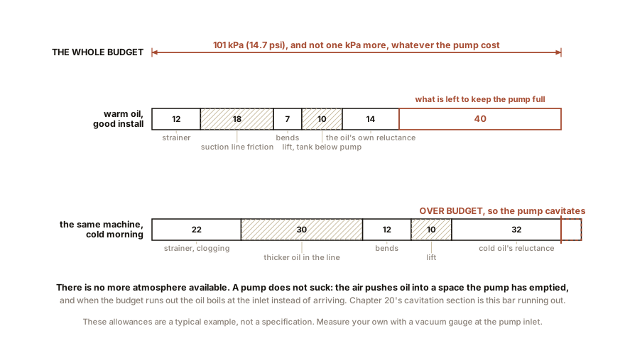
Everything above is about the outlet. Most pump failures happen at the inlet, and the reason is Chapter 5’s ceiling: there is only 101 kPa (14.7 psi) of atmosphere available to push oil into the pump, and it must be enough to overcome the suction line’s friction, the strainer’s resistance, any lift from tank to pump, and the oil’s own reluctance when cold.
Fail to leave enough of that allowance and the absolute pressure at the pump inlet falls low enough that dissolved air comes out of solution and the oil itself begins to vaporise. Bubbles form, get carried into the high-pressure region, and collapse violently. That is cavitation, it sounds like gravel in a tin, and it erodes metal out of the pump’s internals. Chapter 21 covers how to recognise it and how to tell it from aeration, which sounds different and has a different cause.
The design rules that follow are all about generosity on the inlet side: a suction line roughly twice the bore of the pressure line, as short and straight as possible, the reservoir above the pump wherever the layout allows, a strainer sized so that even fully clogged it does not starve the pump, and no fittings that turn the flow sharply. A pump is a poor sucker and a superb pusher.
SLOW DOWN. Check Your Understanding: A workshop replaces a fixed gear pump with a modern pressure-compensated piston pump to save energy. The system worked fine before. Within a month the new pump has failed. Nothing was changed except the pump. What is the most likely cause? Answer before reading on.
Contamination, and the fault was in the system all along. The gear pump was tolerating oil that was dirtier than any piston pump will accept, because a gear pump’s working clearances are larger and its geometry is forgiving: a hard particle passing between a gear tip and the housing scores a groove and the pump carries on at slightly reduced efficiency for years. A piston pump’s slipper rides on a film one or two micrometres thick against a hardened swashplate, and a particle of that size does not pass; it embeds and ploughs. The oil that the old pump lived with for a decade is abrasive slurry to the new one.
So the honest sequence for that upgrade is: flush the system, fit filtration to the pump manufacturer’s specified ISO 4406 code, replace the suction strainer, and check the reservoir for the sludge that a gear pump quietly accumulated. And there is a wider lesson worth taking out of this chapter: a more efficient component is usually a more precise component, and precision is another word for smaller clearances. Upgrading one part of a fluid system without upgrading its cleanliness is the commonest expensive mistake in the field.
The flow exists. The next chapter spends it on doing something, and finds that a cylinder is not as symmetrical as it looks.

Bench Degree
Get the degree without the diploma.
Learn the material, not how to pass the exam.