Bench Degree·FLUID POWERchapter

Chapter 6: Flow Sets Speed, Pressure Sets Force
Two numbers, and almost every misunderstanding in this field comes from treating them as one. A pump does not make pressure. It makes flow, and the load decides the pressure.
Here are the two sentences. They are the whole chapter and they are worth reading twice.
Flow sets speed. Pressure sets force.
And the pump sets the flow, while the load sets the pressure.
The second sentence is the one people fight. Every hydraulic pump has a pressure rating printed on it, catalogues sell pumps by pressure, and shop conversation is full of “a three-thousand-psi pump”. So the idea that the pump does not determine the pressure sounds wrong. It is not wrong, and getting it straight is the difference between being able to think about these machines and having to guess.
Section 1: The Pump Makes Flow
A hydraulic pump is a positive displacement machine, which Chapter 10 covers properly. For now, all it means is this: every revolution of the shaft, the pump traps a fixed volume of oil on the inlet side and carries it round to the outlet. It has no choice about how much. Turn the shaft once and that volume goes out.
So the pump’s honest specification is a volume per revolution, called its displacement. Multiply by the shaft speed and you have the flow.
flow = displacement x shaft speedTake the reference machine used throughout this book: a gear pump that displaces 7 cm³ (0.43 in³) per revolution and, at 1,430 rpm, delivers 10 litres/min (2.6 gal/min).
7 cm3 x 1,430 = 10,010 cm3 per minute = 10 litres/min (2.6 gal/min)Ten litres a minute, and that number does not care what the machine is doing. It is the same when the cylinder is extending against nothing, the same when it is pushing a tonne, the same when it has stalled solid against a wall. The pump is a conveyor belt for oil, and the belt runs at motor speed.
So what sets the pressure? The pump’s outlet oil has to go somewhere. If it can go somewhere freely, the pressure is nearly zero: run a hydraulic pump with its outlet open into the tank and the gauge reads maybe 200 kPa (29 psi), which is just the friction of getting through the pipe. The pressure only rises when something resists.
Section 2: The Load Makes Pressure
Connect the pump to a cylinder with a load on it. The pump pushes oil in. The oil cannot get out. So the pressure climbs, and it climbs until it is high enough to move the load, at which point the piston starts travelling and the pressure stops climbing.
Pressure rises to exactly the value the load demands and no further. That value comes straight from Chapter 5:
pressure needed = force of the load / piston areaPut real numbers on the reference cylinder: 50 mm (2.0 in) bore, 25 mm (1.0 in) rod, 400 mm (16 in) stroke. Piston area is 1,963 mm² (3.04 in²).
| Load on the rod | Pressure the gauge reads |
|---|---|
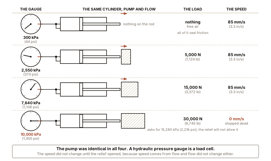
| nothing, free air | about 300 kPa (44 psi), all of it friction |
| 5,000 N (1,124 lb) | 2,550 kPa (370 psi) |
| 15,000 N (3,372 lb) | 7,640 kPa (1,108 psi) |
| 19,600 N (4,410 lb) | 10,000 kPa (1,450 psi) |
| 30,000 N (6,745 lb) | it cannot. See below. |
Read that table until it is obvious. The gauge is not reporting what the pump can do. It is reporting what the load is asking for. A hydraulic pressure gauge is a load cell.
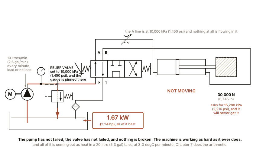
And now the last row. The load asks for 15,280 kPa (2,216 psi) and the system is not allowed to go there, because there is a relief valve set to 10,000 kPa (1,450 psi). So the pressure climbs to 10,000 kPa, the relief opens, and all ten litres a minute goes back to the tank through the valve. The cylinder stops. The pump keeps pumping. And every watt goes into heating the oil, which is Chapter 8 and is the most consequential sentence in the whole subject.
IN PLAIN ENGLISH: A hydraulic pump is like a garden tap you cannot turn down: it delivers a fixed amount of fluid per second, always. If the fluid can escape easily, the pressure is low. If it is being forced to shove something heavy, the pressure gets high. The heaviness of the job decides the pressure, exactly as the weight of a suitcase decides how hard your arm pulls. The tap decides how fast, not how hard.
Section 3: Flow Makes Speed
The other half. Oil arriving into a cylinder has to fill it, and the piston moves out of the way at whatever rate is needed to make room.
speed = flow / areaWatch the units, because this is the one place in fluid power where the arithmetic bites. Two ready-made forms:
speed in mm/s   =  litres per minute  x  16,667  /  area in mm2
speed in in/s   =  gallons per minute x  3.85    /  area in in2
On the reference cylinder at 10 litres/min (2.6 gal/min):
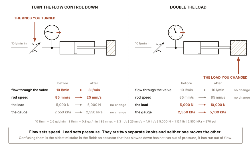
extending: 10 x 16,667 / 1,963 = 85 mm/s (3.3 in/s)So a 400 mm (16 in) stroke takes 4.7 seconds. And that number has nothing to do with the load. Push against nothing and it takes 4.7 seconds. Push against 15,000 N, which is 1,530 kg or 3,372 lb, and it takes 4.7 seconds. The pressure will be wildly different in the two cases and the time will not change, as long as the pressure stays below the relief setting.
The moment the relief opens, of course, all bets are off, because now some of the flow is going somewhere else. A hydraulic actuator that slows down under load has not run out of pressure. It has run out of flow, and the flow went over the relief valve. That distinction is a diagnostic tool and Chapter 21 leans on it.
Retracting is faster, and this catches people every time. On the return stroke the oil pushes on the piston’s other face, which has a hole in it where the rod is. The rod is 25 mm (1.0 in) across, so its area is 491 mm² (0.76 in²) and the effective area on the return is:
1,963 - 491 = 1,472 mm2 (2.28 in2)Less area, so the same flow fills it quicker:
retracting: 10 x 16,667 / 1,472 = 113 mm/s (4.5 in/s)Faster coming back, and weaker coming back, by exactly the same ratio of 1.33. That is the differential area effect, it surprises everybody the first time, and Chapter 11 is largely about it.
Section 4: Feel It With No Equipment At All
This is the cheapest important experiment in the book. It uses the Chapter 1 rig and nothing else.
ON THE BENCH: Prove the two are independent, with two syringes
Parts: the water-filled two-syringe rig from Chapter 1; five hardback books; a phone with a stopwatch. Cost: nothing. Time: 15 minutes. Hazards: none.
Part A: change the speed and leave the load alone. Stand the large syringe upright with two books on the plunger. Push the small plunger through its full travel in 10 seconds, counting. Then do it again in 2 seconds. Then in half a second. What you should feel: the books go up slowly, then quickly, then very quickly, and the effort in your thumb is essentially unchanged. The push you have to supply is set by the books, and the books did not move. You changed the speed by changing how fast you delivered fluid, and the force did not follow.
Part B: change the load and leave the speed alone. Now push the small plunger through its full travel in a steady 5 seconds every time, and do it with two books, then four, then all five plus a bag of sugar. What you should feel: the timing is easy to hold constant, and the effort in your thumb climbs steeply. You changed the force and the speed did not follow.
What you have just done is separate the two variables experimentally, with a ten-dollar rig, which is more than a great many people who work with these machines every day have ever done deliberately. If Part A is hard to feel: you have a bubble. Seal friction and trapped air both add a speed-dependent component and blur the result. Bleed it again.
ON THE BENCH: A bicycle pump is a flow source
Parts: any bicycle pump, ideally one with a gauge; a bicycle or car tyre; your thumb. Cost: nothing. Time: 5 minutes. Hazards: none at these pressures. Do not exceed a tyre’s marked maximum. Method, three parts. First, pump into a soft, nearly flat tyre and watch the gauge: it reads low, perhaps 50 kPa (7 psi), and the handle is easy. Second, pump the same tyre to 400 kPa (58 psi) and notice the handle has become hard. Third, block the outlet completely with your thumb and push: the gauge shoots up as far as your strength allows. What you should see: the pump never chose any of those pressures. In each case the pressure was whatever the thing at the far end demanded, and your arm supplied it. Your arm is the motor, the pump is the displacement, and the tyre is the load. The extra lesson: the number of strokes to fill the tyre is set by the pump’s displacement per stroke, and it is the same whether the tyre is at 50 or 400 kPa (7 or 58 psi). Flow is flow. You have separated speed from force again, with a pump you already own.
Section 5: Where the Confusion Actually Comes From
Three specific places, because naming them stops them recurring.
“A 3,000 psi pump”, meaning 21,000 kPa. What that rating means is: this pump will survive 3,000 psi, or 21,000 kPa, at its outlet without its casing distorting or its seals failing. It is a limit, like the load rating on a rope. It is not an output. A rope rated to a tonne does not pull with a tonne.
“The pump is not making enough pressure.” Almost always wrong, and almost always the load. If a machine will not lift, the honest questions are: is the relief valve set below what the load needs, is the load heavier than the machine was designed for, or is oil escaping past a worn seal or a stuck valve so that the flow is going somewhere other than the cylinder. A worn pump does not lose pressure. It loses flow, which shows up as the machine getting slower rather than weaker, until it is so slow that it cannot outrun the leak and then it appears to lose pressure too. Chapter 21 gives the test that tells these apart in ten minutes.
“Turn up the pressure to make it go faster.” This is the big one, and it is worth being precise about why it sometimes appears to work. If the relief valve is set too low, the machine is spilling flow and raising the setting genuinely does speed it up, because it stops the spilling. That is not the pressure making it faster. That is the flow coming back. Once the relief is above what the load needs, further increases do nothing at all except make the hoses work harder.
Section 6: The Case Where the Load Pushes Back
One more, because it is where the two variables interact and it is the reason for a whole family of valves in Chapter 15.
Suppose the load is not resisting. Suppose it is helping: a heavy platform being lowered, an excavator boom coming down, a load on a hook descending. Now gravity is trying to move the actuator in the direction you asked it to go.
The pressure needed to move it is negative, which is to say the cylinder does not need to be pushed at all and will happily go faster than the pump is filling it. And then the oil on the inlet side is being stretched rather than pushed. The piston runs away from the incoming oil, the pressure at the inlet falls toward zero, dissolved air comes out of solution, and the actuator lurches: it drops, stops, drops again, in a jerky descent that anyone who has lowered a load on a cheap crane has felt.
The fix is to put the restriction on the outlet rather than the inlet, so the fluid leaving the cylinder has to be squeezed out and the load is held back by its own oil. That is called meter-out control and it is Chapter 15’s first section. For now, note the shape of the idea: a runaway load is controlled by what you let out, not by what you put in.
SLOW DOWN. Check Your Understanding: A machine has one pump at 10 litres/min (2.6 gal/min) and two identical cylinders. The operator moves both joysticks at once. Both cylinders have the same load. What happens to the speeds? Now suppose one cylinder has twice the load of the other. What happens then? Answer both before reading on.
With equal loads, the flow divides roughly in half and both cylinders run at half speed, about 42 mm/s instead of 85 mm/s, which is 1.7 inches per second instead of 3.3 inches per second. Slower, and no weaker: each still makes its full force, because pressure is shared and force comes from pressure.
With unequal loads, the answer is uglier and it is the real behaviour of real machines: the light one gets nearly all the flow and the heavy one barely moves. Oil, like current, takes the easy path. The pressure in the shared line rises only to what the lighter load demands, and at that pressure the heavy cylinder cannot move at all. So the light actuator sprints and the heavy one sits still until the light one hits the end of its stroke, at which point the pressure is free to climb and the heavy one finally goes. An excavator that will not curl its bucket while the boom is rising is not faulty; it is a single pump obeying arithmetic. Fixing this is a real design problem with real solutions, flow dividers and pressure-compensated valves and load-sensing pumps, and Chapters 12 and 16 cover all three. The point for now is that you predicted the fault from two sentences of physics.
You can now say how fast and how hard, and which one the designer controls with which component. The next chapter takes the single property that makes a hydraulic machine behave differently from a pneumatic one, and turns it from a word into a number.

Bench Degree
Get the degree without the diploma.
Learn the material, not how to pass the exam.