Bench Degree·FLUID POWERchapter

Chapter 3: The Forgotten Age of Water Power
For a century, several cities piped power under their streets as high-pressure water, sold by the gallon like gas. London’s network ran 296 km (184 miles) of mains at 5,200 kPa (750 psi) and did not close until 1977.
Bramah’s press had one flaw that no amount of better sealing would fix. It had no memory.
The pump made pressure only while somebody was working the handle. Stop pumping and the ram held whatever it was holding, but nothing more could happen. Scale that up to a steam-driven pump feeding a dockside crane, and you have built a machine that must run its engine flat out during the two minutes the crane lifts, and then sit idle burning coal for the twenty minutes while the ship is repositioned. Worse, the engine has to be sized for the crane’s peak demand rather than its average, which on a quayside is a factor of ten.
That is the problem William Armstrong solved, and the solution created a utility.
Section 1: The Crane on the Quay
In 1846 Armstrong, then a solicitor in Newcastle upon Tyne with an expensive hobby, built a hydraulic crane on the town quay. It was driven by the pressure already available in Newcastle’s water main, which is a lovely piece of opportunism: the town had built a pressurised water system to supply houses, and Armstrong noticed that a pressurised water system is a power distribution network that happens to be delivering drinking water.
The crane worked and the orders came in. But the town main gave him only about 200 kPa (29 psi), which is a feeble pressure, and to lift real loads with it he needed absurdly large rams. He needed higher pressure, and higher pressure meant his own pump, and his own pump brought back the peak-demand problem.
Section 2: The Accumulator, Which Is a Battery Made of Water
Armstrong’s answer, developed through the 1850s, is the weighted accumulator, and once you see it the whole utility follows.
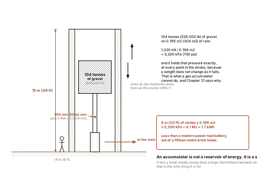
Take a vertical cylinder with a large ram standing in it, open at the top. Load the ram with an enormous dead weight: a cast-iron case filled with gravel, slag or scrap. Connect the bottom of the cylinder to your pipework.
The weight, pressing down on the ram’s area, sets the pressure in the system. And it sets it to one number that never changes. Pump water in and the weight rises. Draw water out and the weight sinks. The pressure at the bottom is the weight divided by the ram area, whatever the height happens to be.
Do the arithmetic on a real one. A ram 500 mm (20 in) in diameter has an area of 196,350 mm² (304 in²). To get 5,200 kPa (750 psi) you need:
5.2 N per square millimetre x 196,350 mm2 = 1,020,000 NThat is 104 tonnes (229,000 lb) of dead weight, sitting on a ram, in a tower. Which is exactly what these things looked like: brick or iron towers 12 to 18 m (40 to 60 ft) tall with a slowly moving weight inside, and you can still find them standing in old dock estates.
Now the pump can be small. It runs steadily all day, filling the accumulator. The cranes draw from the accumulator in violent gulps. A pump sized for the average demand serves a network whose peaks are ten times higher, and the tower absorbs the difference.
And how much does the tower actually store? Take a stroke of 6 m (20 ft):
0.19635 square metres x 6 m  =  1.18 cubic metres  =  1,180 litres (312 gal)
energy  =  pressure x volume  =  5,200,000 Pa x 1.18 m3  =  6.1 MJ
Six megajoules, which is 1.7 kWh. That is the storage of a building-sized structure holding a hundred tonnes of gravel, and it is a third of the energy in a modern cordless drill’s battery pack. Fluid power has never been a good way to store energy and it is not one now, which is worth remembering when Chapter 13 gets to accumulators and Chapter 21 gets to a robot with a pump in its chest. What the accumulator is good at is not capacity. It is smoothing, and delivering a very large power for a very short time.
ON THE BENCH: Build a weighted accumulator
Parts: the 60 mL syringe from Chapter 1; a short length of tubing; a second syringe or a length of hose you can pinch; books; kitchen scales. Cost: nothing. Time: 15 minutes. Hazards: none. Do it over a towel. Method: stand the large syringe upright, full of water, with the plunger up and the tip connected to a pinched tube. Load 5 kg (11 lb) of books on the plunger. That is a force of about 49 N spread over 531 mm² (0.823 in²), so the pressure inside is 92 kPa (13 psi). Now release the pinch slowly and let water out. What you should see: the plunger sinks steadily and the force needed to hold the tube shut does not change as it sinks. You can feel this: pinch the tube, release a little, pinch again, and the resistance is identical at the top of the stroke and at the bottom. Then do the comparison that matters. Repeat with the syringe full of air instead of water and no books, plunger pushed halfway in and the tip blocked. Let a little air out and the pressure immediately falls. A weight gives constant pressure. A trapped gas gives falling pressure. That distinction is the whole design argument in Chapter 13, and it is why a gas accumulator has a usable range rather than a single pressure.
Section 3: A City Plumbed for Power
Once power could be stored, it could be sold. The idea is straightforward and it still sounds strange: bury a high-pressure water main under the street, meter it into buildings, and let each building’s machines run off it.
Hull, on the Humber, had the first public system, opened in 1877 and engineered largely by Edward Bayzand Ellington, who became the field’s great advocate. London followed. The General Hydraulic Power Company was incorporated in 1883, its operating arm became the London Hydraulic Power Company, and it began laying mains under the streets in 1884.
At its height the London network was:
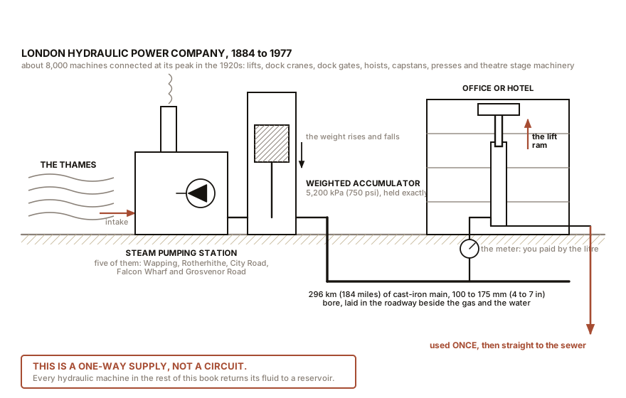
- 296 km (184 miles) of cast-iron main, mostly 100 to 175 mm (4 to 7 in) bore, laid in the roadway alongside the gas and water.
- 5,200 kPa (750 psi), held by weighted accumulators at five pumping stations. Wapping, Rotherhithe, City Road, Falcon Wharf at Blackfriars and Grosvenor Road at Pimlico.
- Roughly 8,000 machines connected at peak, in the 1920s.
- Water drawn from the Thames, pumped by steam engines and later by electric motors, used once, and discharged to the sewers.
What it drove is a list of exactly the jobs fluid power is good at. Passenger and goods lifts in offices and hotels, which is what most of the network was for. Dock cranes and dock gates. Hoists in warehouses. Fire-curtain and stage machinery in theatres, including the sinking and rising stages of the West End. Capstans. Presses in workshops. And the bascules of Tower Bridge, though the bridge had its own pumping plant rather than taking mains supply.
Similar networks ran in Birmingham, Liverpool, Manchester, Glasgow, Antwerp, Geneva, Buenos Aires and Sydney. Melbourne’s system operated from 1889 to 1967. London’s ran until 1977, which means there are people alive who worked on it, and it means high-pressure hydraulic mains and colour television overlapped by a decade.
Section 4: One Detail Worth Its Own Paragraph
The London system was open loop. Water came from the river, did its work, and went down the drain.
Every hydraulic machine in the remaining eighteen chapters of this book is a closed circuit: fluid leaves a reservoir, is pressurised, does work, and returns to the same reservoir to be used again. That single structural difference explains most of what follows in this chapter. An open system must accept whatever the supply water contains, which is why the mains and machines were built of iron in generous sizes and why nobody spoke of filtration to the standards of Chapter 13. It also means the working fluid was free and disposable, and that the system could not be pressurised above the point where leakage became unaffordable.
And it explains the one thing about the London mains that is genuinely charming. When the network closed, the company owned 296 km (184 miles) of continuous, surveyed, dry, empty cast-iron duct running under central London, with access points in every district. Mercury Communications bought it in the 1980s and pulled fibre optic cable through it. The pipes that carried power as water now carry it as light, and a good deal of the City’s data still travels through Victorian hydraulic mains.
Section 5: Why Electricity Ate It
This is the part worth understanding, because the reasons are all in the physics and they will come up again.
Pressure drop with distance is brutal, and it gets worse as you ask for more. Chapter 8 does this properly, but the shape of it is that friction loss in a pipe rises roughly as the square of the flow rate. Double the power demand at the far end of a main and you quadruple the loss getting there. Electricity has the mirror-image problem, losses rising as the square of the current, but electricity has a way out that hydraulics does not: a transformer. Raise the voltage tenfold and the current for the same power falls tenfold and the losses fall a hundredfold. There is no hydraulic transformer. Pressure is pressure, and the only way to move more power down a pipe is a bigger pipe or a higher pressure, and both cost capital in the street.
A main leaks and a cable does not. Every joint in 296 km (184 miles) of buried iron pipe at 5,200 kPa (750 psi) is a maintenance item, and every leak is both a loss and an excavation.
A main freezes. An electric cable does not care about the weather.
And the point-of-use machine got cheap. In 1884 the alternative to a hydraulic lift engine was a steam engine in the basement, and the hydraulic option was obviously better. By 1930 the alternative was a squirrel-cage induction motor, which is compact, silent, needs no water supply, no drain, no accumulator, and costs a fraction as much to install. The utility did not lose on physics. It lost on the price of the thing at the far end of the pipe.
An honest caveat on efficiency. It is often claimed that hydraulic mains were more efficient than early electrical distribution because water is incompressible and therefore nothing is lost to compression. The first half is true and the conclusion does not follow: the losses in a hydraulic main are friction and leakage, and over kilometres of pipe they are substantial. Reliable end-to-end figures for the London system are hard to come by, and the ones quoted in the trade press of the period were written by people selling one technology or the other. What is not contested is that the capital cost of mains in a street was the deciding number, and that is why the last new network was built before the First World War.
ON THE BENCH: Measure the fluid power at your own garden tap
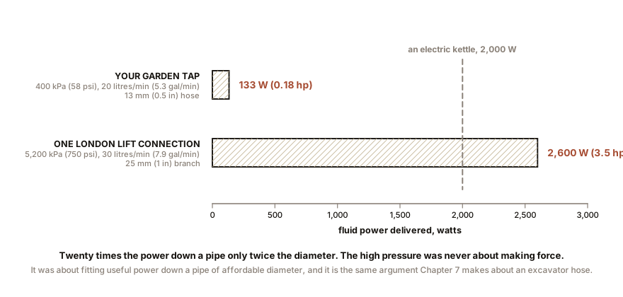
Parts: a hose-bib pressure gauge with a female garden-hose thread, about $12; a bucket of known volume; a stopwatch, or a phone. Cost: $12. Time: 15 minutes. Hazards: none. Do not fit the gauge and then close a downstream valve on a long hose in hot sun, because thermal expansion of trapped water can raise pressure surprisingly fast, and Chapter 22 explains why trapped incompressible fluid is a category of hazard on its own. Method: screw the gauge on the outside tap and open it fully with nothing downstream. Read the static pressure. Then remove the gauge, fill a 10 litres (2.6 gal) bucket, and time it. What you should see: something like 300 to 550 kPa (44 to 80 psi) static, and a fill time of 25 to 40 seconds, which is 15 to 24 litres/min (4 to 6.3 gal/min). Now compute the power, and this is the point of the exercise:
power in kW = bar x litres per minute / 600At 4 bar and 20 litres/min (5.3 gal/min) that is 0.133 kW, which is 133 W. Your garden tap delivers about the fluid power of two bright light bulbs. A kettle uses fifteen times more. Then scale it to London. At 5,200 kPa (750 psi) and 30 litres/min (7.9 gal/min), a single hydraulic lift connection delivered about 2,600 W, and that is why the mains had to be at 750 psi rather than at tap pressure. The pressure is not there to make force. It is there to carry power down a pipe of affordable diameter, and that sentence is the whole design logic of high-pressure hydraulics, arrived at from a bucket and a stopwatch.
IN PLAIN ENGLISH: A pipe can only carry so much fluid per second before friction eats the pressure. So if you want to send more power down a given pipe, you cannot send much more fluid; you have to send it at a higher pressure. That is why hydraulic systems run at pressures that sound alarming. High pressure is not about strength, it is about how much power will fit through a hose you can actually bend.
SLOW DOWN. Check Your Understanding: The London network was abandoned partly because there is no hydraulic transformer. But hydraulics does have a device that changes pressure: a pressure-reducing valve, which takes 5,200 kPa (750 psi) in and gives, say, 1,000 kPa (145 psi) out. Why is that not a transformer? Answer before reading on.
Because a transformer trades voltage for current and keeps the power, while a reducing valve throws the difference away. Drop 5,200 kPa (750 psi) to 1,000 kPa (145 psi) at a given flow and the flow does not increase to compensate; the same flow arrives at a fifth of the pressure, and four fifths of the power has become heat in the valve. That is Chapter 8’s governing fact and it is worth meeting early. There is a hydraulic device that genuinely does trade pressure for flow while keeping the power, and it is not a valve: it is two pumps on a shared shaft, a small one and a large one, sometimes called a hydraulic intensifier or pressure booster. It works, it is used, and the reason it is not a transformer in the useful sense is that it is a rotating machine with bearings, seals and losses, roughly the size of the pump you already have, and you need one at every branch. A transformer is a lump of iron and wire with no moving parts and 99 percent efficiency, and it can be left in a locked cabinet for forty years. That is the asymmetry that decided the twentieth century.
The utility is gone and the physics is not. Everything in the next four chapters is the physics: pressure and area, flow and speed, the compressibility that separates the two halves of the subject, and where the heat goes. Chapter 5 starts with the one equation you will use for the rest of your life.

Bench Degree
Get the degree without the diploma.
Learn the material, not how to pass the exam.