Bench Degree·REFRIGERATIONchapter

Chapter 9: The Four Parts
Four components, settled in 1834 and unchanged since. Two of them are borders, and once you see which two, every refrigeration machine ever built becomes readable.
You have the physics and you have the fluid. This chapter puts the hardware on the bench, one piece at a time, before any of it is connected to anything else.
There are four components. There have been four since Jacob Perkins’s 1834 patent, and there are four in the machines cooling the room in Chapter 21. Learn them once and you can read any refrigeration system, at any scale, for the rest of your life.
But before the four, the division they create.
Section 1: The High Side and the Low Side
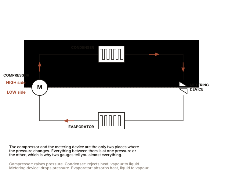
Chapter 7 established that a refrigeration machine is a machine for maintaining two different pressures. That means the loop is not one continuous space. It is two spaces, and the whole thing only works because they stay separate.
The low side is where pressure is low, so the boiling temperature is low, so the refrigerant boils cold and drinks heat out of the place you want cooled.
The high side is where pressure is high, so the condensing temperature is high, so the refrigerant condenses hot and dumps heat into the place you do not care about.
Two of the four components are ordinary pieces of plumbing that live inside one side or the other. Two of them are the borders between the sides, and they are the interesting ones:
- The compressor is the border going from low to high. It raises the pressure.
- The metering device is the border going from high to low. It drops the pressure.
Everything between them on one path is the high side. Everything between them on the other path is the low side.
IN PLAIN ENGLISH: Think of a loop of pipe with two gates in it. One gate pushes fluid through against the pressure, and one gate lets it trickle back. Between them, on one side, is a high-pressure world where the refrigerant condenses hot. On the other side is a low-pressure world where it boils cold. The two gates are the compressor and the metering device, and holding those two worlds apart is the whole job.
Section 2: The Compressor
What it actually does. Not what most people assume. A compressor does not make cold, and it does not primarily pump refrigerant around. It removes vapour from the low side and pushes it into the high side, and by doing so it holds the low side low and the high side high. The circulation is a consequence.
What comes out. High-pressure vapour that is also hot, for the adiabatic reason in Chapter 6. On an R-410A system the discharge line can reach 70 to 105 °C (160 to 220 °F), which is hot enough to burn you and is entirely normal.
The one rule. A compressor is a vapour pump. Vapour compresses; liquid does not. Send liquid into a compressor and it tries to squeeze something incompressible, which is called slugging, and it breaks valves, bends rods and destroys the machine, sometimes in one revolution. Chapter 12’s superheat measurement exists primarily to guarantee this never happens, and Chapter 22 covers what it looks like when it has.
The types, and why each exists:
Reciprocating. Piston and valves, like a tiny engine. Rugged, cheap, tolerant, and the most common type historically. Noisier, and inefficient at part load because it only has one speed.
Scroll. Two interleaved spirals, one fixed and one orbiting, squeezing pockets of vapour progressively inward. Fewer moving parts, far quieter, more efficient, and now dominant in residential and light commercial equipment. Scroll compressors are direction-sensitive: run one backwards on reversed three-phase and it moves nothing and destroys itself, which is a real and common commissioning mistake on the units in Chapter 21.
Rotary vane. A rotor with sliding vanes. Compact and cheap, used in small window units and dehumidifiers.
Screw. Two meshing helical rotors. Large capacities, continuous duty, industrial.
Centrifugal. Not positive displacement at all; it accelerates vapour with an impeller like a jet engine’s. Only sensible at very large capacities, in the chillers of large buildings.
Hermetic, semi-hermetic, open. A hermetic compressor is welded shut with the motor inside, sharing the refrigerant space. Cheap, leak-free, and unrepairable: when it fails you replace it. A semi-hermetic is bolted together and can be opened for repair, which is why commercial equipment uses them. An open compressor has an external shaft and a shaft seal, which is what a car air conditioner has because it is belt-driven by the engine.
ON THE BENCH: Cut one open
Parts: a dead hermetic compressor from a scrap refrigerator or window unit, free from a kerbside or a repair shop; angle grinder or reciprocating saw; gloves; eye and ear protection. Cost: nothing. Time: an hour. Hazards, and read them. Confirm it is empty first. A discarded compressor may still hold refrigerant under pressure, and cutting into a pressurised vessel is dangerous. Open a service port or cut a line with a tubing cutter and let it vent before any grinding. There will be oil inside, and it will run out; work over a tray. Metal swarf and sparks: full eye protection. Method: cut around the girth of the dome and lift the top off. What you should find: an electric motor, sitting in oil, with a small pump on the end of its shaft. Valve plates with reed valves. On a scroll, the two spirals, which are genuinely beautiful. The motor is inside the refrigerant, cooled by the returning suction vapour, which is why a compressor with poor refrigerant return also overheats its own motor. What to take away: you will never again think of a compressor as a mysterious black dome. It is a motor and a pump in a tin of oil.
Section 3: The Condenser
What it does. Takes the hot high-pressure vapour from the compressor and cools it until it turns back into liquid, releasing the latent heat of Chapter 5 into the outdoors.
It does that in three distinct zones, and knowing this is what makes Chapter 12’s subcooling measurement make sense.
Zone one, desuperheating. The vapour arrives hotter than its own condensing temperature, because the compressor superheated it. The first stretch of coil simply cools that vapour down to saturation. Sensible heat only, and this zone is short.
Zone two, condensing. Now on the saturation curve, the vapour turns to liquid at constant temperature while the latent heat pours out. This is most of the coil and most of the heat rejection.
Zone three, subcooling. The last stretch has liquid in it, and continues cooling it below the saturation temperature. That is subcooling, and a few degrees of it is desirable because it guarantees the metering device is fed pure liquid rather than a fizzing mixture.
Air-cooled or water-cooled. Air-cooled is a finned coil and a fan, and it is what almost every domestic and small commercial machine uses. Water-cooled uses a shell-and-tube or plate heat exchanger against a water loop going to a cooling tower, and it is more efficient because water carries heat far better than air, at the cost of a whole second water system to maintain.
The number that matters: condensing temperature runs roughly 11 to 17 °C (20 to 30 °F) above the air going into the coil. So on a 35 °C (95 °F) day, expect condensing around 49 °C (120 °F), which is exactly the figure Chapter 7 used. A dirty coil or a failed fan raises that difference, which raises the pressure, which raises the compressor’s work, which is the commonest cause of a machine that runs but does not cool well.
ON THE BENCH: Measure the heat coming out
Parts: two thermometers or an infrared thermometer; an anemometer if you have one; any running air conditioner or refrigerator. Cost: nothing beyond the kit in The Bench. Time: 15 minutes. Method: measure the air temperature entering the condenser coil and the air leaving it. On a domestic refrigerator, measure the air near the back coils against room air. What you should see: a rise of 5 to 14 °C (10 to 25 °F) across the coil. That temperature rise, multiplied by the airflow and air’s specific heat, is the entire heat output of the machine, and it is the
Q = m c ΔTof Chapter 4 doing real work. If you have an anemometer and the coil dimensions you can compute the machine’s capacity in Btu/h from outside it, without gauges.
Section 4: The Metering Device
The smallest component and the one most people have never heard of. It is also, arguably, the cleverest.
What it does. It is a deliberate restriction. High-pressure liquid arrives at one side; a controlled trickle passes through; on the far side the pressure is low, so the liquid immediately begins to boil. That boiling is the cold.
Why it is a restriction and not a valve you open. The pressure drop is the point. Chapter 6’s adiabatic expansion plus Chapter 5’s latent heat happen precisely because the liquid is forced from a high-pressure region into a low-pressure one.
The types, in order of sophistication:
Capillary tube. A long thin copper tube, typically 0.6 to 1.5 mm (0.024 to 0.060 in) bore and up to several metres long. The restriction is simply friction along its length. Utterly reliable, has no moving parts, costs pennies, and cannot adapt to changing conditions. This is what is in your refrigerator and it will outlive you.
Fixed orifice or piston. A precisely drilled hole in a brass body. Same idea, easier to manufacture to a spec, common in residential air conditioners.
Thermostatic expansion valve (TXV). Now it gets clever. A valve whose opening is controlled by a temperature-sensing bulb clamped to the outlet of the evaporator. If the refrigerant leaving the evaporator is too warm, the coil is starved and the valve opens further. If it is too cold, liquid is getting through and the valve closes down. It regulates itself to maintain constant superheat, which means it adapts to changing load, and it is why commercial equipment uses them.
Electronic expansion valve (EEV). A stepper-motor valve driven by a controller reading sensors. Everything a TXV does, faster, over a wider range, and programmable. Standard on variable-speed and inverter equipment.
IN PLAIN ENGLISH: A capillary tube is a fixed nozzle: it always passes the same trickle regardless of what the machine needs. A thermostatic expansion valve is a nozzle with a brain, watching the far end of the evaporator and adjusting itself so that the refrigerant finishes boiling exactly at the coil’s exit and not before.
ON THE BENCH: Find the pressure drop by hand
Parts: any running refrigerator or window unit. Cost: nothing. Time: 10 minutes. Hazards: hot surfaces near the compressor. Method: trace the small-diameter line leaving the condenser and follow it with a bare hand toward the cold space. What you should feel: somewhere along that path the tubing goes from warm to distinctly cold within a very short distance, sometimes within a few centimetres. That transition is the metering device. On a capillary-tube system it is often soldered alongside the suction line for part of its length, so feel for where the temperature drops sharply. What you have found: the border between the high side and the low side. Everything upstream is high pressure and warm. Everything downstream is low pressure and cold. You just located a pressure boundary with a fingertip.
Section 5: The Evaporator
What it does. The whole point of the machine. Low-pressure liquid arrives, boils at a cold temperature, absorbs the latent heat of Chapter 5 from the air or water passing over the coil, and leaves as vapour.
Three zones again, mirroring the condenser. Mostly boiling at constant temperature, then a final stretch where all the liquid is gone and the vapour warms up a few degrees. That last stretch is superheat, and it is deliberately arranged, for the reason in Section 2: it is the guarantee that no liquid reaches the compressor.
The number that matters: for comfort cooling the coil runs around 4 to 7 °C (40 to 45 °F), which is below the dew point of typical room air, so the coil condenses water out of the air as well as cooling it. That is why an air conditioner has a drain, and why the sensible-versus-latent split of Chapter 14 exists at all.
Why it has fins. Chapter 5’s second trap: refrigerant can only boil as fast as heat can reach it. An evaporator is not sized by how much refrigerant it holds but by how much surface area it presents to the air. Fins multiply that area many times over. Which is why a dirty coil, a blocked filter or a failed fan cripples an otherwise perfect machine: the refrigerant is willing to boil and the heat cannot get to it.
Section 6: The Parts That Are Not Components
Six accessories you will meet on real equipment, each existing for a specific failure.
Filter drier. A cylinder of desiccant and a filter screen in the liquid line. It catches debris and, critically, absorbs water. Water in a refrigeration system freezes at the metering device and blocks it, and combines with refrigerant and oil to form acids that destroy the compressor. It is replaced every time the system is opened, without exception, and Chapter 8’s note about hygroscopic POE oil is why.
Sight glass. A small window in the liquid line. Solid liquid means correct charge; bubbles mean flash gas, which means either undercharge or a restriction upstream. Many have a moisture indicator that changes colour.
Receiver. A liquid reservoir on the high side, used with TXV systems, which need a guaranteed liquid supply and tolerate variable charge.
Accumulator. A vapour-liquid separator on the low side, just before the compressor, which traps any liquid that got through and meters it back slowly. It is insurance against slugging, and heat pumps almost always have one because the reversing valve of Chapter 19 makes liquid return much harder to control.
Service valves. The ports you connect gauges to. On residential equipment they are Schrader valves, like a bicycle tyre.
Crankcase heater. A small band heater on the compressor shell. In cold weather refrigerant migrates and condenses into the compressor’s oil, and starting a compressor full of liquid refrigerant is a flooded start, which is destructive. The heater keeps the oil warm enough to drive it off. This is why some equipment specifies leaving power on to an idle machine, and why switching a heat pump off at the breaker all winter can kill it on restart.
Section 7: Now You Can Read Any Machine
Four components and six accessories, and the two borders that make the whole thing work.
| Part | Which side | What it does |
|---|---|---|
| Compressor | border, low to high | removes vapour from low side, raises pressure and temperature |
| Condenser | high side | rejects heat, vapour becomes liquid |
| Metering device | border, high to low | drops pressure, liquid starts to boil |
| Evaporator | low side | absorbs heat, liquid becomes vapour |
Go and look at any refrigeration machine now, of any kind. A drinks cooler, a dehumidifier, a car’s air conditioner, a rooftop unit on a supermarket. Find the four. The compressor is the heavy thing that hums. The condenser is the coil with warm air coming off it. The evaporator is the coil in the cold place. And the metering device is the small line where warm becomes cold within a few centimetres.
That is the whole taxonomy. In the next chapter, one pound of refrigerant goes round that loop with a real pressure and a real temperature at every station, and the machine stops being a diagram.

Bench Degree
Get the degree without the diploma.
Learn the material, not how to pass the exam.