Bench Degree·REFRIGERATIONchapter

Chapter 10: Walking the Cycle
One pound of R-410A, eight stations, real pressures and real temperatures. This is the chapter where nine chapters of groundwork becomes a machine.
Everything is now in place. You know that boiling absorbs enormous heat and condensing releases it. You know that pressure chooses the boiling temperature. You know the four components and which two are borders. You know what fluid is in there and why.
So take one pound (0.45 kg) of R-410A and follow it all the way round, once.
The machine is an ordinary residential air conditioner, three tons, cooling a house on a summer afternoon. Conditions are the ones this book has been using since Chapter 7, and they are typical rather than special:
- Indoor air entering the evaporator: 24 °C (75 °F)
- Outdoor air entering the condenser: 35 °C (95 °F)
- Low side pressure: 820 kPa (119 psig), so saturation temperature 4 °C (40 °F)
- High side pressure: 2,930 kPa (425 psig), so saturation temperature 49 °C (120 °F)
Everything below follows from those four lines.
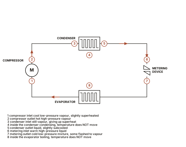
Section 1: Station 1, the Compressor Inlet
Pressure 820 kPa (119 psig). Temperature 11 °C (52 °F). State: superheated vapour.
Our pound of refrigerant arrives at the compressor as vapour, entirely. No liquid at all, and this matters enormously: Chapter 9’s one rule is that a compressor is a vapour pump and liquid destroys it.
Notice that the temperature, 11 °C (52 °F), is higher than the 4 °C (40 °F) that this pressure would give a saturated fluid. That difference of 7 °C (13 °F) is superheat, and it is the deliberate margin that guarantees the vapour is dry. It was created in the last stretch of the evaporator, at station 8, and Chapter 12 is about measuring it.
The vapour is cool to the touch and low in density. It is also carrying a little oil back to the compressor in the form of a mist on the pipe walls, which is why suction lines must be sized and sloped correctly.
Section 2: Station 2, the Compressor Outlet
Pressure 2,930 kPa (425 psig). Temperature 88 °C (190 °F). State: hot superheated vapour.
The compressor has done its work. Pressure has risen by a factor of about 3.6, and the temperature has gone from 11 °C to 88 °C (52 °F to 190 °F).
That temperature rise is Chapter 6 in action. The compressor squeezed the vapour fast, no heat escaped during the squeeze, and the work put in became internal energy. Nothing was heated. Work was done, and the vapour has become hot as a consequence.
This is the discharge line, and it is the hottest point in the entire system. On a real machine it is genuinely hot enough to burn a hand. That is normal, and a discharge line that is not hot on a running machine is a symptom, usually of a compressor that is not compressing.
Note what has and has not changed. Pressure up, temperature up, and the refrigerant is still vapour. No condensing has happened yet, because the vapour at 88 °C (190 °F) is well above its own saturation temperature of 49 °C at this pressure. It is superheated by 39 °C (70 °F), and the first job of the condenser is to get rid of that.
SLOW DOWN. Check Your Understanding: The compressor consumed electrical energy to do this. Where did that energy go? Think before reading on.
Into the refrigerant, as heat. It is now part of the 88 °C (190 °F) vapour, and it will be rejected out of the condenser along with the heat picked up from the house. This is why an air conditioner rejects more heat outdoors than it removes indoors: the outdoor coil has to get rid of the house’s heat plus the compressor’s electrical input. A three-ton unit removing 36,000 Btu/h (10.5 kW) while drawing 3.5 kW rejects about 14 kW outdoors. It is also why a refrigerator with its door open heats the kitchen rather than cooling it.
Section 3: Stations 3 and 4, Through the Condenser
Station 3, condenser inlet: 2,930 kPa (425 psig), 88 °C (190 °F), superheated vapour. Station 4, condensing begins: 2,930 kPa (425 psig), 49 °C (120 °F), saturated vapour.
Outdoor air at 35 °C (95 °F) is being blown across the coil. The refrigerant at 88 °C (190 °F) is much hotter than that air, so heat flows out of the refrigerant into the air. Downhill, as it always must.
In the first stretch of coil, all that happens is the vapour cools. Sensible heat only, no change of state, temperature falling from 88 °C toward 49 °C (190 °F toward 120 °F). This is the desuperheating zone of Chapter 9, and it is a short part of the coil because sensible heat is a feeble carrier.
At station 4 the vapour reaches 49 °C (120 °F), which for 2,930 kPa (425 psig) is exactly the saturation temperature. It is now sitting on the curve from Chapter 7.
And now the temperature stops falling.
For most of the remaining coil length, the refrigerant condenses at a constant 49 °C (120 °F) while dumping its latent heat into the outdoor air. Chapter 5’s plateau, running in the release direction. This is where nearly all the heat rejection happens, and it is why the middle of a condenser coil is all at much the same temperature while the inlet end is markedly hotter.
You can verify that with a bare hand or an infrared thermometer on any running outdoor unit, and it is worth doing, because seeing a coil that is 88 °C (190 °F) at one end and 49 °C (120 °F) over most of its length makes the phrase “latent heat” concrete.
Section 4: Station 5, the Condenser Outlet
Pressure 2,930 kPa (425 psig). Temperature 41 °C (105 °F). State: subcooled liquid.
All the vapour has condensed. Our pound of refrigerant is now entirely liquid, and the last stretch of coil has continued to cool it, to 41 °C (105 °F).
That is 8 °C (14 °F) below its saturation temperature of 49 °C (120 °F), and that margin is subcooling. It is deliberate and it matters for a specific reason: it guarantees that what arrives at the metering device is solid liquid rather than a mixture of liquid and bubbles. A metering device fed bubbles passes far less refrigerant than one fed liquid, and the machine’s capacity collapses.
Subcooling is the second of the two numbers every technician measures. Together with superheat it tells you almost everything about the charge and the health of a system, which is Chapter 12.
Section 5: Stations 6 and 7, Across the Border
Station 6, metering device inlet: 2,930 kPa (425 psig), 41 °C (105 °F), subcooled liquid. Station 7, metering device outlet: 820 kPa (119 psig), 4 °C (40 °F), mostly liquid with some vapour.
This is the most dramatic transition in the whole loop and it happens in a few centimetres.
The liquid is forced through the restriction. On the far side the pressure has collapsed from 2,930 to 820 kPa (425 to 119 psig), a factor of 3.6. And at 820 kPa the saturation temperature is 4 °C (40 °F), so a liquid that arrived at 41 °C (105 °F) is now 37 °C (67 °F) hotter than its own boiling point.
So it boils. Instantly and violently.
And here is the mechanism that makes the whole machine work. Nothing has heated the refrigerant and nothing has cooled it from outside. It cools itself. Some fraction of the liquid, roughly a quarter, flashes to vapour immediately, and the latent heat required to do that is stolen from the liquid that remains. The remaining liquid is chilled to 4 °C (40 °F) as payment.
That fraction is called flash gas, and it is the price of admission. About 25 percent of your pound has become vapour without absorbing any heat from the house at all, purely to cool the other 75 percent down to working temperature. Only that remaining 75 percent is available to do useful cooling.
IN PLAIN ENGLISH: Squeeze a hot liquid into a low-pressure space and part of it boils off, and the boiling chills what is left. The refrigerant cools itself down to working temperature by sacrificing a quarter of itself. Nothing external did the cooling.
This is also precisely why subcooling at station 5 matters. Arrive with more subcooling and less of your pound needs to flash away, so more of it is left to do useful work. Every degree of subcooling buys capacity.
Section 6: Stations 8 and Back to 1, Through the Evaporator
Station 7 to 8: 820 kPa (119 psig), a constant 4 °C (40 °F), liquid boiling to vapour. Station 8 to 1: 820 kPa (119 psig), warming from 4 °C to 11 °C (40 °F to 52 °F), superheated vapour.
Indoor air at 24 °C (75 °F) is blown across the evaporator coil. The refrigerant inside is at 4 °C (40 °F). Heat flows downhill out of the room air and into the refrigerant, and the refrigerant uses it to boil.
This is the useful part of the whole machine, and it happens at constant temperature. The refrigerant absorbs its latent heat, 75 Btu/lb (174 kJ/kg), while sitting stubbornly at 4 °C (40 °F). The coil is the same temperature all the way along, which is exactly what you want, because it means the whole coil surface is working at maximum effect.
Along the way, the room air passing over the coil is cooled from 24 °C to about 13 °C (75 °F to 55 °F), and because 13 °C is below the dew point of ordinary room air, water condenses out of it onto the fins and runs to the drain. That is a second, separate job the coil is doing, and Chapter 14 is entirely about it.
At station 8 the last of the liquid boils away. From there to station 1 the vapour, now dry, warms up by another 7 °C (13 °F) as it travels the rest of the coil and the suction line. That is the superheat we started with, and the loop is closed.
Our pound of R-410A is back where it began, having carried a load of heat out of the house and dumped it in the garden, and it will do it again in the next few seconds.
Section 7: The Whole Thing in One Paragraph
Worth memorising, because it fits.
Cold low-pressure vapour enters the compressor, which squeezes it into hot high-pressure vapour. The condenser cools that vapour with outdoor air until it condenses to liquid, releasing its latent heat outdoors. The liquid passes through a restriction into a low-pressure region, where part of it flashes to vapour and chills the rest. That cold liquid boils in the evaporator, absorbing latent heat from indoor air, and leaves as cold low-pressure vapour, which enters the compressor.
Five sentences. Every refrigerator, freezer, air conditioner, heat pump, chiller and drinking fountain on earth.
Section 8: What Heat Went Where
The accounting, because it settles a question people ask.
Heat in, at the evaporator: the useful cooling. For a three-ton machine, 36,000 Btu/h (10.5 kW) taken out of the house.
Work in, at the compressor: about 3.5 kW of electricity for that duty on a decent machine.
Heat out, at the condenser: the sum of both. About 14 kW (48,000 Btu/h) rejected outdoors.
Which yields the number Chapter 13 is about: 10.5 kW of cooling for 3.5 kW of electricity is a coefficient of performance of 3.0. Three units of heat moved per unit of electricity spent, for exactly the reason Chapter 19 gives about heat pumps: the machine is not making cold, it is moving heat, and the electricity pays for the moving.
Section 9: The Table
Every station, both unit systems, one place.
| Station | Where | Pressure | Temperature | State |
|---|---|---|---|---|
| 1 | compressor inlet | 820 kPa / 119 psig | 11 °C / 52 °F | superheated vapour |
| 2 | compressor outlet | 2,930 kPa / 425 psig | 88 °C / 190 °F | hot superheated vapour |
| 3 | condenser inlet | 2,930 kPa / 425 psig | 88 °C / 190 °F | superheated vapour |
| 4 | condensing begins | 2,930 kPa / 425 psig | 49 °C / 120 °F | saturated vapour |
| 5 | condenser outlet | 2,930 kPa / 425 psig | 41 °C / 105 °F | subcooled liquid |
| 6 | metering inlet | 2,930 kPa / 425 psig | 41 °C / 105 °F | subcooled liquid |
| 7 | metering outlet | 820 kPa / 119 psig | 4 °C / 40 °F | liquid plus flash gas |
| 8 | boiling complete | 820 kPa / 119 psig | 4 °C / 40 °F | saturated vapour |
Read down the pressure column and you see two numbers, not eight. The whole loop is two pressures, with the changes happening only at stations 1 to 2 and 6 to 7, which are the two borders. That is Chapter 7’s lever, visible as a column of figures.
Section 10: Doing It On a Real Machine
ON THE BENCH: Gauges on both sides
Parts: gauge manifold matched to the refrigerant, $60 to $140; two pipe clamp thermometers; a running air conditioner, ideally a scrap window unit. Cost: the manifold, which lasts a career. Time: 45 minutes. Hazards, and they are real. Gloves and eye protection. Liquid refrigerant causes instant frostbite and blinds. The high side runs at 2,900 kPa (425 psig); never open it to atmosphere. Venting refrigerant deliberately is illegal in most jurisdictions and every hose connection loses a little, so learn on scrap. The discharge line is hot enough to burn. Method: connect low side to the suction port and high side to the liquid port. Record both pressures. Convert each to a saturation temperature with the card from Chapter 7. Then clamp thermometers to the suction line near the evaporator outlet and to the liquid line near the condenser outlet, and record actual metal temperatures. Then fill in your own version of the Section 9 table. You will have stations 1, 5, 7 and 8 measured directly, and the rest inferred. What you should find: superheat of 4 to 8 °C (8 to 15 °F) and subcooling of 5 to 11 °C (10 to 20 °F) on a healthy machine. Then change something. Block half the condenser airflow with cardboard and watch the high side pressure climb, the condensing temperature rise, and the compressor work harder. Restore it. Block the evaporator’s return air filter and watch the low side pressure fall. You have just simulated the two commonest faults in the trade, and Chapter 22 covers what they do over months rather than minutes.
ON THE BENCH: Walk the loop with a bare hand
Parts: a running refrigerator. Nothing else. Cost: nothing. Time: 10 minutes. Method: starting at the compressor, follow every pipe with your fingers and narrate the stations out loud. What you should find: compressor dome warm, discharge line hot, condenser coil hot at the inlet end and merely warm at the outlet, liquid line warm, then a sharp transition to cold where the capillary tube begins, then cold all the way through the evaporator, then a cool suction line returning. Eight stations, one hand, no instruments. If you can do that and say what state the refrigerant is in at each point, this chapter has done its job.
Section 11: What Comes Next
The machine is now fully explained. Everything from here is either measurement, arrangement, or failure.
Chapter 11 builds something. Chapter 12 takes the superheat and subcooling numbers you just met and turns them into a diagnostic method. Chapter 13 puts the whole cycle on a single chart and computes its efficiency. And Part VI opens up real equipment, starting with the simplest complete machine there is: a window unit, which is everything in this chapter mounted on one chassis with a wall running through the middle of it.

Bench Degree
Get the degree without the diploma.
Learn the material, not how to pass the exam.