Bench Degree·SOLAR POWERchapter

Chapter 8: Efficiency, and the Ceiling
Measure the area of your own panel, measure the sunlight falling on it, measure what comes out, and divide. The answer will be somewhere near a fifth, and this chapter accounts for the other four fifths, item by item, until there is nothing left unexplained.
You can measure your panel’s true efficiency in twenty minutes, and it is worth doing before reading the explanation, because a number you found yourself is harder to argue with.
Three measurements.
The area. Not the glass, and not the frame. The active area, which is the cells. For the Chapter 1 panel, the outside dimensions are 1,000 by 670 mm (39.4 by 26.4 in), so 0.67 m² (7.2 ft²) of aperture.
The sunlight arriving. You need irradiance in watts per square metre, and the cheapest accurate way to get it is a second, small cell whose short-circuit current at standard conditions you know. Because short-circuit current is proportional to irradiance, as Chapter 6 established, the ratio gives you the answer directly. A dedicated solar irradiance meter costs about $35 and does the same arithmetic inside.
The power out at the maximum power point, found with the rheostat from Chapter 7.
Then:
efficiency = power out / (irradiance x area)
On a good clear day you might measure 880 W/m² and 88 W out:
88 / (880 x 0.67) = 88 / 590 = 0.149
Fifteen percent. The nameplate said 100 W, and it
was honest: at 1,000 W/m² and 25 °C (77 °F) the panel would indeed
produce 100 W, giving 100 / 670 = 14.9 percent. The panel
is doing what it promised. It is simply that fifteen percent is
what a cheap panel is, and 85 percent of the sunlight landing
on it is going somewhere else.
This chapter is a full accounting of where.
ON THE BENCH: Measure your own panel’s efficiency
Parts: your panel; a tape measure; a rheostat and two meters from Chapter 7; and either a solar irradiance meter, about $35, or a small cell of known rated Isc. Cost: about $35 if you buy the meter. Time: 30 minutes on a clear day near noon. Hazards: none. Method: measure the panel’s cell area, not its glass area, and note both in m² and ft². Take irradiance in the plane of the panel, not horizontally: hold the reference cell flat against the panel’s glass. Find the maximum power point with the rheostat. Divide. What you should see: 14 to 16 percent for a cheap panel, 19 to 22 percent for a good modern module. Then compare against the nameplate:
nameplate watts / (1,000 x area in m²), and the two should agree within a couple of percentage points. What to notice: your measured figure will usually come out below the nameplate figure, and the gap will be larger in the afternoon than in the morning. Write down the panel’s back-surface temperature every time. Chapter 9 is that gap. If your efficiency comes out above the nameplate: you have almost certainly measured glass area instead of cell area, or measured irradiance on a horizontal surface while the panel was tilted toward the sun.
Section 1: The First Loss Is in the Spectrum
Chapter 4 already delivered this one, and it is the largest single item.
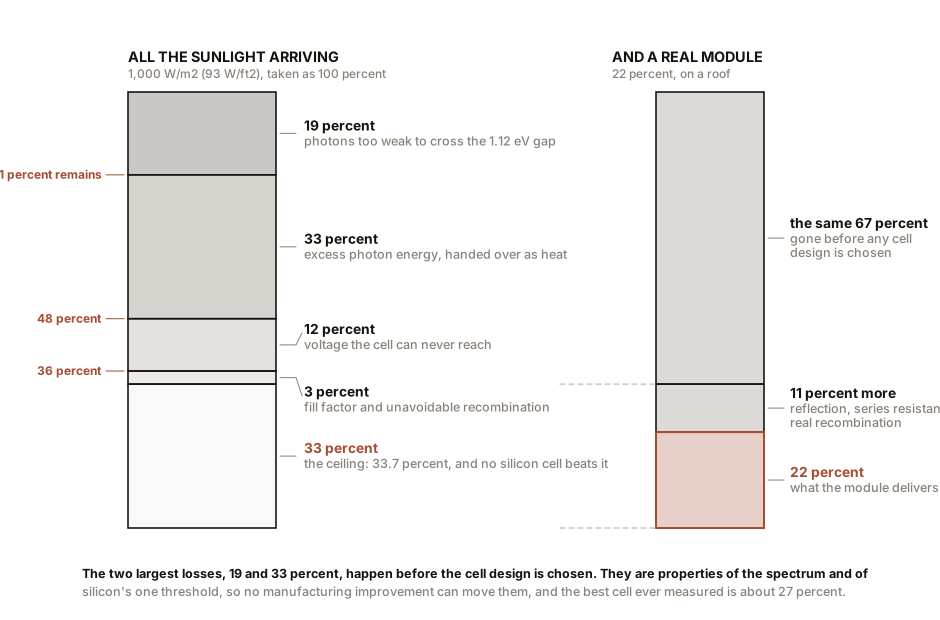
Photons carrying less than silicon’s 1.12 eV cannot free an electron. They pass through, or they warm the cell, and either way they produce nothing. That is everything beyond 1,107 nm, and it is about 19 percent of the energy in sunlight.
Nothing can be done about it with silicon. Not better manufacturing, not thinner wafers, not a cleverer contact grid. The photons are the wrong colour and silicon has one threshold.
Running total: 81 percent remains.
Section 2: The Second Loss Is the Change
This one is less obvious and it is bigger than most people expect.
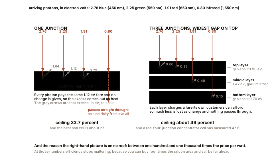
A blue photon carries 2.76 eV. Silicon’s gap is 1.12 eV. What happens to the extra 1.64 eV?
The photon lifts an electron high into the conduction band, well above the bottom of it. Within about a picosecond, that electron loses its excess energy by bumping into the crystal lattice, sliding down to the bottom of the conduction band, and the excess comes out as heat.
Every photon delivers exactly one electron’s worth of usable energy, equal to the band gap, and hands over everything above that as warmth. A blue photon and a red photon, arriving at the same silicon cell, do precisely the same electrical work. The blue one merely makes the panel hotter while doing it.
That is the fact that makes this loss so large. Silicon’s gap corresponds to 1,107 nm, out in the infrared, and most of the sun’s energy arrives at much shorter wavelengths than that. Averaged over the whole spectrum, the excess given up as heat is about 33 percent of the incoming energy.
Running total: 48 percent remains.
IN PLAIN ENGLISH: Think of the cell as a turnstile that charges a flat fare of 1.12 electron volts. A photon with less than the fare cannot get through and its money is wasted. A photon with more than the fare gets through and no change is given. Blue light is a customer paying two and a half times the fare and walking away with nothing back. Between the ones who cannot afford it and the change that is never returned, the turnstile has lost half its takings before anything else goes wrong.
Section 3: The Third Loss Is Voltage That Never Appears
Silicon’s gap is 1.12 eV, so you might expect a silicon cell to produce 1.12 V. It produces about 0.62 V, as Chapter 6 both calculated and measured.
Roughly 45 percent of the voltage is missing, and it is missing for a reason no amount of engineering removes.
You have already measured this, on a driveway, in Chapter 1. When you plotted open-circuit voltage against reciprocal wavelength for a handful of LEDs, the line did not pass through the origin. It cut the voltage axis about half a volt low, and every LED in the set came out under its own photon energy by roughly that amount. That intercept was not sloppy measurement. It was this loss, and you found it before you had any theory to explain it. Dig the plot out and read the intercept off it; that number is what the rest of this section is about.
Go back to the Voc equation from Chapter 6:
Voc = n x Vt x ln(IL / I0 + 1)I0 is not zero and cannot be made zero. A cell at any
temperature above absolute zero is generating electron-hole pairs
thermally, and it is also emitting light, faintly, in
the infrared, because any warm object emits and a good absorber is
necessarily a good emitter. Those two processes set a floor under
I0, and that floor sets a ceiling under
Voc.
That sentence is worth more than it looks, because it runs in
both directions. A cell that emits its light cleanly, rather
than losing carriers to defects first, has the lowest possible
I0 and therefore the highest possible Voc.
Turn it around and you get a working rule that the industry actually
uses: a great solar cell must be a great LED. The
relationship is quantitative. Every factor of ten a material loses in
light-emitting efficiency costs it about 60 mV of open-circuit
voltage.
This is why the single-junction efficiency record, 29.1 percent, belongs to gallium arsenide and not to silicon. GaAs is a direct-gap material and an outstanding emitter, which is exactly why it made the first good infrared and red LEDs, and the same property buys it the voltage. Silicon is indirect, is a poor emitter, and pays for it here. When someone wants to know whether a new photovoltaic material has any future, the fastest test is not to shine light on it and look for current. It is to run current through it and see whether it glows.
A cell has to be a good absorber to work, and being a good absorber makes it an emitter, and being an emitter costs it voltage. There is no way to be one without the other. That is the deepest constraint in this chapter and the one people find hardest to accept.
Add the fill factor from Chapter 7, which even an ideal cell cannot push past about 0.89 because the diode’s exponential is what it is, and the accounting closes.
Running total: about 33 percent.
ON THE BENCH: Catch the energy going the other way
Parts: two identical panels, 10 to 50 W, about $30 each; a rheostat or a fixed resistor near the panel’s maximum power point; two thermocouple thermometers or one infrared thermometer, about $20; a windless clear day. Cost: about $80, or nothing if you already own two panels. Time: an hour. Hazards: none. Method: mount both panels side by side, same tilt, same airflow, and leave them in the sun for twenty minutes to settle. Then load one panel at its maximum power point and leave the other open circuit, connected to nothing. Wait another twenty minutes. Measure the back-surface temperature of each, in the same spot on each, several times. What you should see: the open-circuit panel running hotter than the loaded one, by roughly 1 to 3 °C (2 to 5 °F). Why that is the whole chapter in one measurement: both panels are absorbing the same sunlight. The loaded one is exporting about fifteen percent of it down a wire. The open-circuit one is exporting nothing, so every joule it absorbs has to leave as heat instead. The temperature difference is the energy you are extracting, showing up as an absence. Be honest about the limits of this one. The effect is small, and a breeze, a slightly different mounting, or the sun moving will produce differences of the same size. Take many readings, swap which panel is loaded halfway through, and treat a result under 1 °C (2 °F) as inconclusive rather than as a refutation. This is a genuinely marginal measurement and it is worth doing anyway, because knowing which of your experiments are marginal is most of what separates a measurement from a number.
Section 4: The Shockley-Queisser Limit
In 1961 William Shockley and Hans-Joachim Queisser published the calculation this chapter has just walked through, done properly, and produced a number.
For a single-junction cell in the terrestrial solar spectrum, the maximum possible efficiency is about 33.7 percent, at an optimum band gap of 1.34 eV.
The assumptions are few and they are all physics rather than engineering: one band gap, sunlight arriving unconcentrated, and the only loss mechanism being the radiative emission a cell cannot avoid. Add nothing about materials, manufacturing or contacts.
For silicon specifically, at 1.12 eV rather than the optimum 1.34, the limit is about 32.3 percent. Include one further unavoidable loss mechanism specific to silicon, an interaction called Auger recombination in which two carriers annihilate and hand their energy to a third, and the practical ceiling comes down to about 29.4 percent. That refinement is from a 2013 calculation by Richter and colleagues, and it is the figure the silicon industry now treats as its wall.
Here is where reality actually sits:
| Efficiency | |
|---|---|
| Shockley-Queisser, optimum gap | 33.7 percent |
| Shockley-Queisser, silicon | 32.3 percent |
| Silicon including Auger recombination | 29.4 percent |
| Best silicon cell ever measured in a laboratory | about 27 percent |
| Best commercial silicon module | 22 to 24 percent |
| Typical good commercial module | 20 to 22 percent |
| Cheap module, the one on your bench | 14 to 16 percent |
The laboratory record is within about two and a half percentage points of a limit set by physics. That is an extraordinary place for an industry to be, and it has a hard consequence: panel efficiency is essentially finished as a source of improvement. Whatever makes solar cheaper from here will not be a better cell.
Section 5: How Multi-Junction Cells Beat It, and Why They Are Not on Your Roof
The Shockley-Queisser limit assumes one band gap, and both of the two big losses come from that assumption. A single gap is too high for the red end of the spectrum and too low for the blue end at the same time.
So use more than one.
Stack cells with different gaps, widest gap on top. The top cell takes the blue photons and extracts their large energy properly. Everything it cannot use passes through to a cell beneath with a smaller gap, which takes the green and red. What that one cannot use passes to a third for the infrared.
Each layer charges a fare appropriate to its own customers, so much less is lost as change and much less passes through unconverted.
The limits rise accordingly. Two junctions: about 42 percent. Three: about 49 percent. An infinite stack, with concentrated sunlight: about 86 percent, which is a mathematical curiosity rather than an engineering target.
Real devices have got remarkably close. The record for a multi-junction concentrator cell is 47.6 percent, a four-junction device measured at Fraunhofer ISE under sunlight concentrated 665 times. That is not a projection. It is a measurement on a real part.
So why is your roof covered in 22 percent silicon instead of 47 percent gallium arsenide?
Cost, by two or three orders of magnitude. Multi-junction cells are grown layer by layer from vapour onto expensive substrates, in a process that takes hours per wafer and cannot be scaled the way silicon has been. Per watt, they are somewhere between a hundred and a thousand times the price of silicon. At those numbers efficiency stops mattering, because you can simply buy four times the silicon area and still be far ahead.
The two places they win are the two places where area or weight is priced above money: satellites, where a launch costs thousands of dollars per kilogram, and concentrator systems, where a small expensive cell sits at the focus of a large cheap lens. Concentrated photovoltaics had a serious run in the 2010s and lost to plain silicon on cost, and there is very little of it being built today.
The live frontier is different, and it is tandems on silicon. Perovskite-on-silicon tandem cells have reached about 34.6 percent in the laboratory, using a cheap solution-processed top layer on an ordinary silicon bottom cell. That is above the silicon-only limit of 29.4 percent, and it is achieved with a manufacturing route that might plausibly be affordable.
Whether it becomes a product is genuinely open. Perovskites degrade under heat, humidity and ultraviolet light, and no one has yet demonstrated a twenty-five year outdoor lifetime. That is the whole question, and it is a stability question rather than an efficiency question. What would settle it is field data from installed modules over a decade, which by definition does not exist yet.
Section 6: One Note on Ceilings
Worth an aside, because it explains why the numbers in this chapter feel unfamiliar to anyone who has met efficiency limits elsewhere.
A solar cell converts photons one at a time. Each arriving photon either promotes one electron across the gap or does not, and the ceiling on the process comes from counting photons and the energy each one carries. That is the accounting this chapter has done.
A steam turbine or an engine works on a different accounting entirely. It takes in heat at one temperature, rejects it at a lower one, and the fraction it can convert to work is limited by the ratio of those two temperatures. A plant taking steam at 600 °C (1,112 °F) and rejecting to a river at 25 °C (77 °F) faces a ceiling near 66 percent and achieves perhaps 45.
Two ceilings, two derivations, two different sets of variables. The photovoltaic limit does not depend on the temperature of the sun and the surroundings in the way an engine’s does, which is why a solar cell can be compared usefully against 33.7 percent and not usefully against anything a turbine is measured by. It is also why cooling a solar cell helps it, a fact that surprises people whose intuition was built on engines, and which Chapter 9 is finally about to explain.
SLOW DOWN. Check Your Understanding: Two panels, side by side on the same roof, same area of 2 m² (21.5 ft²) each. Panel X is 22 percent efficient and costs $180. Panel Y is 15 percent efficient and costs $95. Per watt, Panel Y is cheaper:
95 / 300 = $0.32/Wagainst180 / 440 = $0.41/W. So the cheap panel wins on the only metric that matters. Under what circumstances is that reasoning wrong, and what does that tell you about who should care about efficiency? Answer before reading on.The reasoning is wrong whenever the roof is the scarce resource rather than the money.
Work it. A roof with space for exactly sixteen modules gets 7.04 kW of Panel X or 4.80 kW of Panel Y. If the household needs 7 kW to cover its usage, Panel Y cannot get there at any price, and the comparison is over. The cheap panel is not cheap; it is unavailable.
Now the other side of it. Everything that is not the module scales with area or with count rather than with watts: the racking, the roof penetrations, the labour to lift and bolt sixteen frames, the wiring runs, the permit. Chapter 3’s arithmetic said modules are ten to fifteen percent of an installed residential system. Choosing the cheaper, less efficient panel saves you money on ten percent of the job and costs you more on the other ninety, because you need forty-six percent more of everything.
So: efficiency matters to whoever is short of area, and price per watt matters to whoever is short of money and has area to spare. A utility-scale developer with a hundred hectares of scrubland buys on price per watt and is right to. A homeowner with one south-facing roof plane buys on efficiency and is also right. And your bench panel at 15 percent is the correct choice for a bench, where the only scarce resource is twenty dollars.
Chapter 9 is the one that pays for this book: what the panel on the roof actually produces once temperature and shade have had their turn.

Bench Degree
Get the degree without the diploma.
Learn the material, not how to pass the exam.