Bench Degree·SOLAR POWERchapter

Chapter 6: The P-N Junction and Why It Makes Current
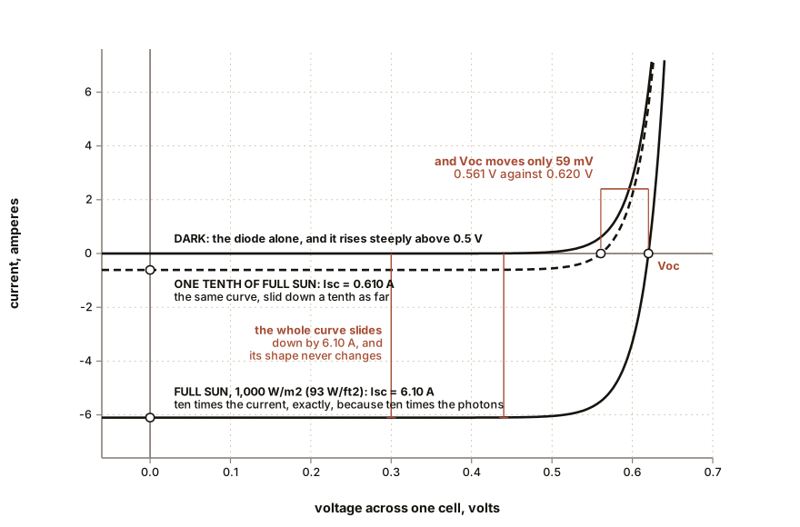
Measure a solar cell in the dark with a battery and a resistor and it behaves exactly like an ordinary diode, because that is what it is. Then put it in the light and the whole curve slides downward without changing shape. Everything in this book comes out of that one slide.
Get the small cell or panel from Chapter 1, a 9 V battery, a 100 Ω resistor and two multimeters, and work in a dark room or with the cell face down on a table.
Wire the battery, the resistor and the cell in series so that the battery drives current into the cell’s positive terminal. Measure the voltage across the cell with one meter and the current through it with the other. Then vary the battery voltage by swapping in a 4.5 V or 3 V battery pack, and record several pairs.
The cell conducts. Above about half a volt per cell it passes current freely, and the current rises very steeply for small increases in voltage. Now reverse the battery and repeat.
Almost nothing. Microamps, and they barely change however much reverse voltage you apply, up to the point where you should stop.
That is a diode. Not something like a diode, not a diode-shaped device. A solar cell in the dark is a diode, and a large-area one at that, and it will show you the same asymmetric curve as the 1N4148 from Chapter 5.
ON THE BENCH: A solar cell is a diode in the dark
Parts: the Chapter 1 cell or a single loose cell, about $3; a 9 V battery and a 3 V pair of AA cells; a 100 Ω resistor and a 1 kΩ resistor; two multimeters, or one meter used twice. Cost: under $10 above what you already own. Time: 45 minutes. Hazards: none. Keep the current below a couple of hundred milliamps so nothing gets warm. Method: work in the dark, and check first that the cell reads zero volts open circuit so you know it is truly dark. Forward-bias it through the resistor and record voltage across the cell against current through it, for as many battery and resistor combinations as you can arrange. Then reverse and repeat. What you should see: a single cell begins to conduct near 0.45 V and is conducting hard by 0.6 V. A 36-cell panel does the same thing at 36 times those voltages, so about 16 V to 22 V. In reverse, currents of microamps to a few milliamps, roughly independent of voltage. Then plot it, with voltage on the horizontal axis and current on the vertical, using the same axes you will use in Chapter 7. Keep the plot. You are going to draw a second curve on it in the next box, and the relationship between the two is the point of this chapter. If forward current runs away: your resistor is too small. The cell has almost no resistance of its own once it is conducting, so the resistor is what limits the current, and 100 Ω across 9 V is already 90 mA.
Section 1: What Happens at the Boundary
Chapter 5 left two pieces of silicon touching: n-type with spare electrons, p-type with spare holes. Pick up the story there.
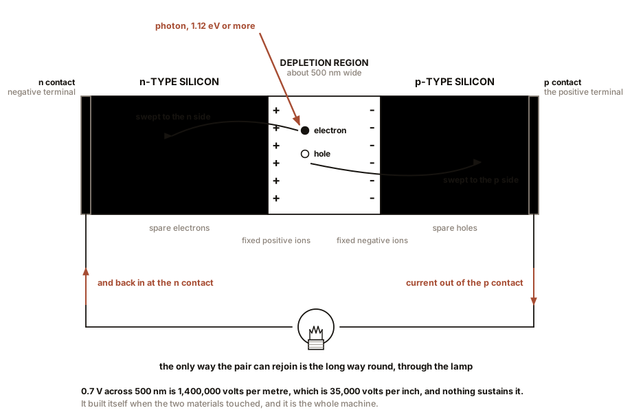
Electrons cross from the n side into the p side, where holes are waiting, and recombine. Holes cross the other way and are filled. Within a very short distance of the boundary, every mobile carrier has been used up, and that carrier-free region is called the depletion region. In a typical solar cell it is somewhere between 300 nm and 1,000 nm wide, which is a hundredth of the thickness of a sheet of paper.
Look at what the departed carriers left behind.
On the n side, each phosphorus atom that donated an electron is now a fixed positive ion, locked in the crystal lattice, unable to move.
On the p side, each boron atom that accepted an electron is now a fixed negative ion, equally immobile.
So the depletion region has a sheet of fixed positive charge along its n edge and a sheet of fixed negative charge along its p edge, with nothing mobile in between. Fixed charge separated by a gap is a built-in electric field, and for silicon at ordinary doping levels it corresponds to a potential step of about 0.6 to 0.7 V across that tiny distance.
Which means the field strength is enormous. Take 0.7 V across 500 nm and the field is 1.4 million volts per metre, which is 35,000 volts per inch. That is not far off the field that will spark across dry air, and it exists permanently inside every solar cell, sustained by nothing.
The process is self-limiting, which is the neat part. Every electron that crosses makes the field slightly stronger, and the field opposes further crossings. Diffusion pushes carriers across; the field pushes them back; equilibrium arrives within a fraction of a nanosecond of the two materials touching, and nothing more happens until something disturbs it.
IN PLAIN ENGLISH: Join the two kinds of silicon and the loose electrons near the join immediately fall into the nearby vacancies, leaving a narrow strip in the middle with nothing loose in it. The atoms they came from and went to are now charged and stuck. So the strip has plus signs along one edge and minus signs along the other, and a very steep electrical slope across it. Nobody built that slope. It built itself, and it is the machine.
Section 2: The Photon Arrives
Now shine light on it, and specifically, land a photon of at least 1.12 eV somewhere in or near the depletion region.
The photon is absorbed. Its energy lifts one electron out of the valence band and into the conduction band, which leaves behind exactly one hole. One photon, one electron-hole pair. That is the accounting, and Chapter 4 already used it to predict a current.
Here is the problem that had to be solved and that the junction solves. That electron and that hole are created a few atoms apart, they attract each other, and left alone they will recombine within microseconds and release the energy again as heat. A photon absorbed in plain silicon produces a brief flicker of nothing.
But the pair was not created in plain silicon. It was created inside a field of a million volts per metre, and that field does not treat the two carriers alike.
The field sweeps the electron toward the n side and the hole toward the p side. They are pulled apart within picoseconds, far faster than they could find each other again, and once separated by the width of the depletion region they are effectively out of reach of one another.
The electron is now on the n side, in a region full of electrons where it is unremarkable and stable. The hole is on the p side, likewise. The pair has been split and banked, and the two halves cannot get back together except by going the long way round: out through the n contact, along a wire, through whatever load you connected, and back in through the p contact.
That trip through the wire is the current, and it is the only thing a solar cell does.
And now the LED from Chapter 1 makes complete sense. An LED is a p-n junction with a contact on each side, exactly like the cell you just measured. Drive current into it and electrons are pushed across the junction to meet holes, and each recombination releases the band gap’s worth of energy as one photon. Shine light on it instead and the process runs backwards: photons arrive, pairs are created, the built-in field separates them, and current comes out. The same field, the same gap, the same junction, and the only difference is which direction the energy is travelling. Which is also why a red LED and a blue LED read different voltages in the same sunlight: their band gaps differ, so the fare differs, so the voltage differs.
Section 3: Why This Is Not a Battery
Worth pausing on, because the intuition trips almost everybody.
A battery holds a finite quantity of chemical reagents and runs down. A solar cell holds nothing and consumes nothing. The electrons leaving the n contact are the same electrons arriving at the p contact, going round in a loop. The silicon is not used up, and nothing in the cell is consumed except the photon, which was not yours to begin with.
That is why the operating life of a photovoltaic module is set by encapsulation, adhesives, backsheets and connectors, all of which are Chapter 14’s subject, and not by the silicon. The silicon does not wear out. Vanguard 1’s cells from Chapter 3 stopped working because of radiation damage in orbit, not because they ran low on anything.
And it is why a cell in the dark produces nothing at all, unlike a battery, which sits at its terminal voltage indefinitely. No photons, no pairs, no current. The device is a converter, not a store, which is exactly why Chapter 12 has to talk about batteries as a separate machine.
Section 4: One Equation for Both Curves
The forward and reverse behaviour you measured in the dark is described by an equation from 1949, and it is worth having because everything in Chapter 7 falls straight out of it.
I = I0 x (exp(V / (n x Vt)) - 1)I0 is the reverse saturation current, the tiny leakage
you measured going backwards, and for a silicon cell it is of the order
of a fraction of a nanoamp. n is the ideality factor,
between 1 and 2 for real devices. Vt is the thermal
voltage, and it is the term that matters most in this book:
Vt = kT / q = 25.7 mV at 25 °C (77 °F)That is 25.7 millivolts, and it is a measure of how much energy the ambient heat is handing out to individual carriers. It rises with temperature, in direct proportion to absolute temperature, and remember that, because it is coming back.
Now add the light. Illuminate the cell and it generates a
photocurrent, call it IL, that flows in the reverse
direction and does not depend on the voltage across the cell at all. It
depends only on how many photons are arriving. So:
I = IL - I0 x (exp(V / (n x Vt)) - 1)That is the whole model, and look at what it says: the light
term is a constant subtracted from the dark diode curve. The
shape of the curve does not change when you illuminate the cell. The
entire curve simply slides down the current axis by IL.
That is what the next bench box shows, and it is a genuinely satisfying thing to see on your own graph paper.
ON THE BENCH: Slide the curve with sunlight
Parts: everything from the first box, plus the sun, plus graph paper. Cost: nothing more. Time: an hour on a clear day. Hazards: none. Method: repeat the forward-bias measurements from the first box, outdoors, with the cell in full sun and the same battery-and-resistor combinations. Plot the new points on the same axes as the dark curve. What you should see: the same curve, the same shape, the same steepness, displaced downward by a constant amount everywhere. That constant is the photocurrent, and it equals the short-circuit current you get by simply shorting the illuminated cell through your ammeter. The two crossings are the two numbers everyone quotes. Where the illuminated curve crosses zero current is the open-circuit voltage. Where it crosses zero volts is the short-circuit current. You have now derived both of them from a diode equation and a lamp, and Chapter 7 is about the fact that neither of them is where you should operate. Then shade it to a tenth with four layers of insect screen, and plot a third curve. Notice how far the short-circuit current falls and how little the open-circuit voltage does. Section 5 explains why, and it is the most useful asymmetry in the subject.
Section 5: Voltage Is Logarithmic, Current Is Linear
Set the total current to zero in the equation above, which is what an open-circuited cell does, and solve for V:
Voc = n x Vt x ln(IL / I0 + 1)That logarithm is the reason for the asymmetry you just measured.
Short-circuit current is proportional to light. Ten times the photons, ten times the current, and the relationship is very nearly a straight line over four or five orders of magnitude. That is why the selenium exposure meter in Chapter 3 worked as a light meter on the current scale.
Open-circuit voltage rises with the logarithm of light. Ten times the photons buys you an extra:
n x Vt x ln(10) = 1 x 25.7 mV x 2.303 = 59 mV per cell
Fifty-nine millivolts. That is all. A hundred times the light gives you 118 mV. A thousand times gives 177 mV.
Put real numbers on it. Take a cell with a photocurrent of 6.1 A in full sun and a saturation current of 0.2 nanoamps:
Voc = 25.7 mV x ln(6.1 / 0.0000000002) = 25.7 mV x 24.14 = 0.620 V
0.620 V per cell, and the 36 cells of the Chapter 1 panel wired in series give 22.3 V, against the 22.0 V on its nameplate. A single equation, one measured leakage current, and the nameplate falls out to within two percent.
Three things follow immediately, and all three matter later.
A cell’s voltage barely moves between bright and dim. This is why your LED in Chapter 1 read over a volt in direct sun and still read most of that in the shade. It is also why a solar-powered garden light works at dusk: it still has voltage, it simply has almost no current.
Every silicon cell produces about 0.6 V, and nothing you do changes that. Not the cell’s size, not its manufacturer, not the price. Cell area sets current. Cell chemistry sets voltage. A cell the size of a dinner plate and a cell the size of a postage stamp both sit at about 0.6 V, which is why panels have dozens of cells in series and why Chapter 10 is about wiring.
And Vt is proportional to absolute
temperature. Look back at the equation for Voc and
you might expect a hotter cell to give a higher voltage, since
Vt gets bigger. It does not, and the reason is that
I0 climbs far faster with temperature than Vt
does, roughly doubling every 10 °C (18 °F). A bigger I0
shrinks the logarithm, and the shrinking beats the growing by a wide
margin. Net result: about 2 mV lost per cell per degree Celsius,
which is 1.1 mV per degree Fahrenheit, and that number is
Chapter 9’s whole subject.
SLOW DOWN. Check Your Understanding: A manufacturer builds two cells from the same wafer, same material, same process. Cell A is 10 mm square (0.4 in square). Cell B is 160 mm square (6.3 in square), so 256 times the area. In identical sunlight, what is the ratio of their open-circuit voltages, and what is the ratio of their short-circuit currents? Answer before reading on.
Currents: 256 to 1, near enough exactly, because current comes from counting photons over an area.
Voltages: 1 to 1. Not 256 to 1, and not 16 to 1. Identical, to within a few millivolts.
The reason is worth having, because it is not obvious from the equation at first glance. Both
ILandI0scale with area: a bigger cell collects more photons and leaks more in the dark, in the same proportion. So the ratioIL / I0inside the logarithm is unchanged, and the voltage does not move.That is why voltage is a material property and current is a geometry property, and it is the most useful division in the whole subject. It tells you that a panel’s voltage is set by how many cells are in series, full stop, which is how you read an unfamiliar nameplate: divide the open-circuit voltage by about 0.62 and you have the cell count, whether or not the label mentions it. Try it on the panel in front of you.
Chapter 7 takes the illuminated curve you plotted and asks the only question that matters about it: where on that curve should the panel actually be made to sit?

Bench Degree
Get the degree without the diploma.
Learn the material, not how to pass the exam.