Bench Degree·SOLAR POWERchapter
Chapter 10: Wiring, Series and Parallel
Four small panels, wired three different ways, produce the same forty watts and lose one percent, four percent and sixteen percent of it in the same length of wire. The wiring is not a detail. It is the difference between a system and a heater.
Buy four small panels, 10 W each, about $18 apiece. Each has an open-circuit voltage near 22.0 V and a short-circuit current near 0.61 A, with a maximum power point at 18.0 V and 0.56 A.
Wire them three ways and measure each.
| Configuration | Voc | Isc | Vmp | Imp | Power |
|---|---|---|---|---|---|
| All four in series | 88.0 V | 0.61 A | 72.0 V | 0.56 A | 40 W |
| Two series pairs, in parallel | 44.0 V | 1.22 A | 36.0 V | 1.12 A | 40 W |
| All four in parallel | 22.0 V | 2.44 A | 18.0 V | 2.24 A | 40 W |
Forty watts, three times. Series adds voltage and leaves current alone. Parallel adds current and leaves voltage alone. Power is the product, so it does not care.
Now connect each arrangement to a load through 30 m (98 ft) of 18 AWG wire, which is a plausible run from a shed roof to a shed, and work out what the wire eats. Eighteen gauge copper is about 21 milliohms per metre, so 30 m (98 ft) out and the same back is 1.25 Ω of round trip.
Power lost in a wire is current squared times resistance:
series: 0.56² x 1.25 = 0.39 W
two by two: 1.12² x 1.25 = 1.57 W
parallel: 2.24² x 1.25 = 6.27 W
One percent, four percent, sixteen percent. The same panels, the same sunlight, the same wire, and a factor of sixteen in the loss, because the current went up by four and the loss goes as the square.
That is the whole reason arrays are high voltage, and you can measure it in an afternoon.
ON THE BENCH: Four panels, three ways, one wire
Parts: four small panels, 10 W each, about $18 apiece; 60 m (197 ft) of 18 AWG wire, about $12; MC4 connectors or screw terminals; a rheostat; two multimeters. Cost: about $95, and the panels are useful forever. Time: three hours on a clear day. Hazards: four panels in series reach 88 V open circuit, which you can feel and would rather not. Wire and unwire them in the shade or covered, never in sun. Do not go beyond four in series for this experiment. Method: for each of the three configurations, measure Voc, Isc, and the maximum power point twice: once with the meters right at the panels, and once with the 60 m (197 ft) of wire between the array and the load. Subtract. What you should see: identical power at the panels in all three cases, and losses in the long wire that quadruple each time you halve the voltage. Also notice that the voltage drop you can measure directly with a meter across the two ends of the wire: about 0.7 V in series, 1.4 V in the two-by-two, 2.8 V in parallel. The subtle result worth chasing: in the parallel case the loss is large enough to shift the array’s operating point, so the maximum power point you find with the wire in place sits at a slightly different voltage than without it. The wire is not a passive spectator; it is part of the circuit the tracker is trying to optimise. If your numbers do not quadruple: measure your wire’s actual resistance with the meter, shorting the far end. Real spool wire varies, and cheap “copper” wire is sometimes copper-clad aluminium with 60 percent more resistance.
Section 1: The Rule, and What It Costs
Two sentences and everything in this chapter follows.
In series, voltages add and the current is common. Eight modules of 38.8 V make 310.4 V, and every one of them carries the same 13.5 A. If one of them can only supply 3 A, the string carries 3 A, which is Chapter 9’s shading problem restated.
In parallel, currents add and the voltage is common. Sixteen modules of 13.5 A make 216 A, all at 32.6 V.
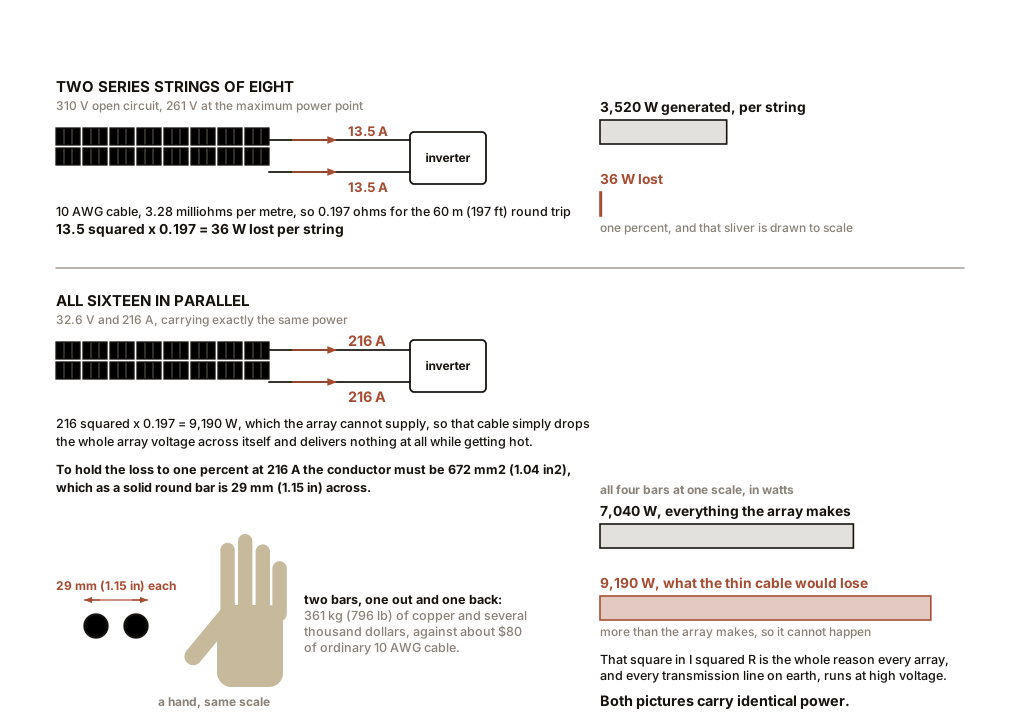
Now take the real array from Chapter 13, sixteen modules of 440 W, so 7.04 kW, and run it 30 m (98 ft) from the roof to the inverter. Compare the two extremes.
Wired as two series strings of eight, each string carries 13.5 A at 261 V. Standard 10 AWG photovoltaic cable is 3.28 milliohms per metre, so the 60 m (197 ft) round trip is 0.197 Ω.
13.5² x 0.197 = 36 W lost out of 3,520 W per string, which is 1.0 percent
Wired as sixteen parallel modules, the whole array is at 32.6 V and 216 A. Through the same cable:
216² x 0.197 = 9,190 W
Which is impossible, since the array only makes 7,040 W. The cable would simply drop the entire array voltage across itself and deliver nothing at all, while getting extremely hot.
So size a cable that could do the job. To hold the loss to one percent, 70 W, at 216 A, you need a round-trip resistance of 0.0015 Ω over that 60 m (197 ft) round trip. Copper’s resistivity says that requires a conductor cross-section of about 672 mm², which is 1.04 in². As a solid round bar, that is 29 mm (1.15 in) in diameter.
Two copper bars an inch and a quarter thick, thirty metres out and thirty metres back, to deliver seven kilowatts. Together they would weigh about 361 kg (796 lb) and cost several thousand dollars. Against 0.197 Ω of ordinary 10 AWG cable at maybe $80.
That is why arrays are high voltage, and there is
nothing more to it than the square in I²R.
IN PLAIN ENGLISH: Sending power down a wire is like sending water down a pipe. You can push a lot of water slowly through a wide pipe or a little water fast through a narrow one. Electrically, high voltage is the “slowly” option: the same power moves with far less current, and it is current that heats the wire. Double the voltage and you halve the current and quarter the loss. Every long-distance power line in the world exists because of that one sentence, and so does every solar array.
Section 2: The Ceiling on Voltage, and Where It Comes From
If higher voltage is better, why stop at 310 V? Why not wire all sixteen in series and get 620 V?
Because of the cold.
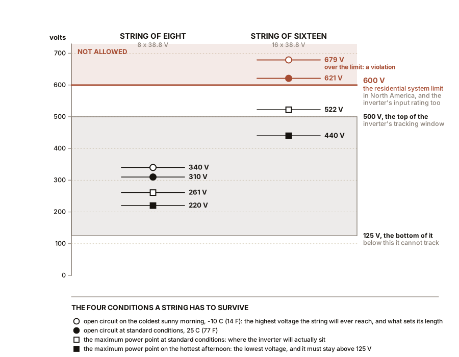
Chapter 9’s temperature coefficient runs both ways. A module’s open-circuit voltage rises as it gets colder, at 0.27 percent per degree Celsius for the module in question, which is 0.15 percent per degree Fahrenheit. So the number to design against is not the nameplate voltage. It is the voltage on the coldest sunny morning the site will ever see.
Work it for a site whose record low is −10 °C (14 °F), which is 35 degrees Celsius below standard test conditions:
string of 8: 8 x 38.8 x (1 + 0.0027 x 35) = 310.4 x 1.0945 = 340 V
string of 16: 16 x 38.8 x 1.0945 = 679 V
In North America, residential photovoltaic systems are limited to 600 V. A string of sixteen would exceed that on any cold clear morning, and would exceed the 600 V rating of the inverter’s input as well. A string of eight has 260 V of headroom.
The limits are worth knowing because they explain the shape of every installation you will ever see:
| Application | Maximum system voltage |
|---|---|
| Residential, North America | 600 V |
| Commercial rooftop | 1,000 V |
| Utility-scale ground mount | 1,500 V |
Higher voltage means fewer, longer strings and thinner cable, which is why a solar farm is built at 1,500 V and a house is not. The reason a house is held to 600 V is firefighters and untrained occupants, and it is a deliberate trade of efficiency for safety.
And notice which coefficient you design against. String length is set by the cold open-circuit voltage, and the inverter’s tracking window is set by the hot maximum power point voltage. The two ends of the temperature range constrain the design from opposite directions, and squeezing between them is most of what array design is. For the array here: eight modules give 340 V on the coldest morning, under the 600 V ceiling, and about 220 V at their hottest, well above the inverter’s 125 V lower tracking limit. Comfortable at both ends.
Section 3: Why DC Is Harder to Switch Than AC
This is the part of the chapter that is about not getting hurt, and the physics is genuinely different from mains wiring.
When you pull two live contacts apart, current keeps flowing for a moment through the ionised air between them. That is an arc. It is a plasma, it runs at several thousand degrees, it will burn through metal, and it lengthens as you pull the contacts further apart rather than breaking.
Alternating current puts an end to its own arcs. At 50 or 60 Hz the current passes through zero a hundred or a hundred and twenty times a second, and at each zero crossing the arc loses its supply, cools, and stops conducting. An AC switch only has to survive until the next zero crossing, which is at most ten milliseconds away.
Direct current has no zero crossings. An arc struck in a 340 V DC string is supplied continuously, and it will keep burning as long as the source can sustain roughly 15 to 20 V across it, which a solar string can do across a gap of several millimetres. It does not stop. It has to be forcibly extinguished, by stretching it, cooling it, or splitting it across multiple contacts.
Three consequences, all of them practical.
A DC breaker or switch is a physically larger and more expensive device than an AC one of the same rating, full of arc chutes and magnets designed to blow the arc apart. An AC-rated switch used on DC will weld itself shut, and this is a real and common installation error.
Never unplug a photovoltaic connector under load. The MC4 connectors on the back of every module are not switches and are not rated to break current. Cover the array, or open the inverter’s DC isolator first, then unplug. A connector pulled apart at 13 A and 340 V will strike an arc that damages both halves, and the damage may not be visible, and the resulting high-resistance joint becomes Chapter 14’s most common failure.
And a solar array cannot be turned off. This is the one that catches people. A switch downstream stops current flowing, but the modules are still generating voltage, and the DC cable from the array to that switch is still live at several hundred volts. The only off switch on a solar panel is darkness, and even a firefighter’s floodlight is enough to put a hazardous voltage on those conductors.
ON THE BENCH: See the voltage drop, and prove it goes as the square
Parts: one panel of 50 to 100 W; 30 m (98 ft) of thin wire, 20 or 22 AWG, about $8; a rheostat; two multimeters. Cost: about $10 beyond earlier boxes. Time: an hour. Hazards: the thin wire will get warm. Do not coil it tightly while running current through it. Method: run the panel to the load through the long thin wire. Put one meter across the two far ends of the wire itself, reading the drop along it, and the other in series reading the current. Now vary the rheostat to step the current through several values, from about a quarter of the panel’s short-circuit current up to nearly all of it, recording drop and current at each. What you should see: the drop rising in proportion to current, exactly as Ohm’s law says. Then compute the power lost in the wire at each point, being drop times current, and plot it against current. That plot is a parabola, and the point at the far right, at full current, is four times the point at half current. The number to take away: divide the lost power by the panel’s output at each step. That percentage is what the wire is costing you, and it is the number a system designer chooses cable size to control. Two percent is the usual target for the DC side of an installation. Then do the honest version: repeat with proper 10 AWG cable and watch the loss become almost unmeasurable. The experiment that shows the problem and the experiment that shows the fix are the same experiment run twice.
Section 4: Rapid Shutdown, and What Drove It
The fact that an array cannot be switched off created a specific and serious problem, and the problem was fires.
A firefighter cutting a ventilation hole in a burning roof, at night, under floodlights, is cutting through a surface covered in glass panels whose wiring is at several hundred volts DC and which cannot be de-energised from the ground. Boots on a wet roof. Axes through cable. There were injuries, and there were fire departments that adopted a policy of letting houses with solar arrays burn down rather than send crews onto the roof.
That is what rapid shutdown requirements were written to fix. In the United States they appear in Article 690.12 of the National Electrical Code, introduced in the 2014 edition and tightened in 2017.
The 2014 requirement was that conductors running more than a short distance from the array be reduced to a low voltage within seconds of a shutdown signal, so that the cable running down the wall and into the house was safe.
The 2017 requirement went to the array itself: within the array boundary, conductors must fall to 80 V or less within 30 seconds. That effectively mandates electronics at each module, because the only way to de-energise the wiring between panels is to put a switch inside every panel’s own circuit.
Which is worth noticing, because it changes Chapter 9’s economics. The comparison there priced module-level electronics against a plain string inverter as an optional upgrade bought for shade tolerance. In jurisdictions enforcing module-level rapid shutdown, they are not optional, and the marginal cost of choosing optimisers or microinverters over a plain string inverter is much smaller, because the plain string inverter now needs a rapid-shutdown device at each module anyway.
Codes vary by country and by year and this book cannot tell you what applies to your roof. What it can tell you is what question to ask: does my jurisdiction require module-level shutdown, because the answer changes which architecture is cheapest, not merely which is better.
Section 5: Fusing, and Why Solar Fuses Are Peculiar
One last wiring matter, and it is a nice illustration of how a solar array is not like other electrical sources.
A fuse protects a wire from a fault current larger than the wire can carry. That logic assumes the source can deliver much more current than normal when something goes wrong, which is true of a battery, a generator or a grid connection.
A solar module cannot. Its short-circuit current is only about 6 percent above its operating current, as Chapter 7’s curve shows: 14.3 A shorted against 13.5 A working. A dead short across a single module is barely distinguishable from normal operation, and no fuse will ever notice it.
So the fusing in a photovoltaic array protects against a different thing: current flowing backwards into a faulted string from the other strings in parallel with it. Three strings in parallel can push their combined current into a fourth that has developed a short, and that reverse current can be several times what the faulted string’s wiring was sized for.
Which yields the rule you will see in every installation manual, and now it makes sense: string fuses are required once you have three or more strings in parallel, and not before, because with only two strings neither can push more into the other than that other one was already built to carry.
And the wire sizing rule has a similar flavour. Codes require photovoltaic source circuit conductors to be rated for 156 percent of the module’s short-circuit current, which is 1.25 for the possibility of irradiance above 1,000 W/m² on a bright day with cloud-edge enhancement, times 1.25 for continuous duty. For the 440 W module at 14.3 A that is 22.3 A, which puts you on 10 AWG cable.
SLOW DOWN. Check Your Understanding: An installer offers to save you money by wiring your sixteen modules as four parallel strings of four instead of two strings of eight. Same modules, same inverter, same total power, less string voltage, so it sounds safer. Name three things that get worse, and one that gets better. Answer before reading on.
Worse, first. Four strings of four sit at 130 V at their maximum power point, half of the two-string arrangement. Each string’s cable still carries the same 13.5 A, but now it is carrying half as much power, so the loss as a fraction of output doubles, from 1.0 percent to 2.0 percent. That is another 94 kWh a year given away permanently, and it never comes back.
Second, 130 V may fall outside the inverter’s tracking window on a hot day. A string’s maximum power point voltage falls at about 0.40 percent per degree Celsius, which is 0.22 percent per degree Fahrenheit, steeper than its open-circuit voltage does. At 65 °C (149 °F) a four-module string drops to about 110 V, and the inverter’s lower tracking limit is 125 V. On the hottest afternoons the array would fall off the bottom of the inverter’s range and shut down entirely, which is a spectacular and confusing failure that only happens in a heatwave.
Third, four parallel strings require string fusing by the rule above, which is more hardware, more connections and more things to corrode.
Better: shading tolerance, slightly. With four short strings rather than two long ones, a shadow that lands on one string leaves three quarters of the array unaffected rather than half. If the roof genuinely has a shading problem, that is worth something, though module-level electronics address it far better.
The point of the question is the second item, because it is the one nobody expects. A design can be correct at 25 °C (77 °F) and fail completely at 40 °C (104 °F), and the failure is not a burnt component but an inverter that simply stops finding a valid operating point. Every string calculation has to be run twice, at the coldest morning and at the hottest afternoon, and a design that passes only one of them is not a design.
Chapter 11 takes the several hundred volts of direct current this chapter has assembled and turns it into a sine wave that a grid you do not control will accept.

Bench Degree
Get the degree without the diploma.
Learn the material, not how to pass the exam.