Bench Degree·WIND POWERchapter

Chapter 5: The Betz Limit
This is the summit of the book. Four lines of algebra, no calculus, and at the end of it a number that no machine anyone builds in the next thousand years will exceed.
You already know the shape of the argument, because Chapter 1 gave it to you in words.
Take nothing from the wind and you get nothing. Take everything from the wind, meaning bring the air to a dead stop, and the stopped air blocks the rotor, no more air can get through, and you also get nothing. Between those two zeros there is a maximum. This chapter finds it exactly.
The result is that the best possible rotor of any design, in any wind, takes 16/27 of the power passing through its swept area, which is 59.3 percent. Albert Betz published it in 1919 and it has never been threatened.
What follows is the actual derivation. It takes about a page, it uses only conservation of mass and conservation of momentum, and the most demanding step is factorising a difference of two squares. If you have followed the book to here you can follow this, and it is worth the effort, because the number means something quite different once you have watched it arrive.
Section 1: The Trick, Which Is to Refuse to Describe the Rotor
The reason Betz’s answer applies to machines that had not been invented is that he never says what the rotor is.
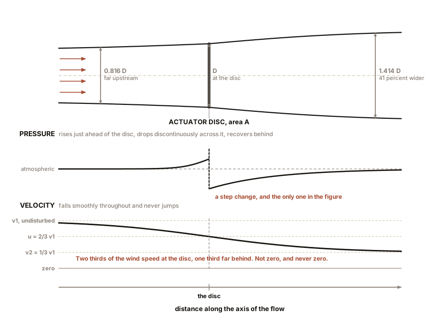
He replaces it with an actuator disc: a permeable surface of area A, standing across the flow, which extracts energy from the air passing through it and applies a uniform thrust to it. No blades. No rotation. No airfoils, no blade count, no tip-speed ratio, no material. Just a disc that takes energy out.
This is not a simplification that gets refined later. It is the whole point. Any real machine that takes energy from a stream of air must, whatever it looks like, slow that air down and push against it. So whatever a real machine does, an actuator disc can do at least as well, because the disc has no drag, no friction, no swirl and no finite number of anything. The disc is therefore an upper bound on every machine, including machines nobody has thought of.
That is why the shrouded rotor and the bladeless mast and the electrostatic converter of Chapter 8 are all bound by this result. Not because they resemble a propeller. Because they take energy from moving air.
Three velocities matter, all measured along the axis of the flow:
- v₁, the wind speed far upstream, undisturbed.
- u, the wind speed at the disc.
- v₂, the wind speed far downstream, in the fully developed wake.
And immediately there is something worth noticing. The stream tube must get wider as it goes through. Mass is conserved, and if the air is slowing down then the same mass per second needs more area to fit through. So the tube of air that ends up passing through the rotor was narrower than the rotor upstream, and is wider than the rotor downstream. That expansion is real, it is visible in Chapter 9’s wake photographs, and it will give us a number at the end.
Section 2: The Derivation
Step one. Mass flow. The mass of air passing through the disc each second is the density times the area times the speed at the disc:
ṁ = ρ A uStep two. Thrust, from momentum. The force on the disc equals the rate of change of the air’s momentum, which is the mass flow times the change in velocity from far upstream to far downstream:
T = ṁ (v₁ − v₂) = ρ A u (v₁ − v₂)Step three. Thrust again, from pressure. The same thrust is the pressure difference across the disc, times its area. Applying Bernoulli’s relation separately upstream of the disc and downstream of it, and noting that the pressure recovers to atmospheric at both far ends, the pressure jump across the disc comes out as
Δp = ½ ρ (v₁² − v₂²)so that
T = ½ ρ A (v₁² − v₂²)Step four, which is the whole trick. Set those two expressions for thrust equal to each other.
ρ A u (v₁ − v₂) = ½ ρ A (v₁² − v₂²)Factorise the right-hand side as a difference of two squares:
ρ A u (v₁ − v₂) = ½ ρ A (v₁ − v₂)(v₁ + v₂)Divide both sides by ρA(v₁ − v₂), and everything collapses:
u = (v₁ + v₂) / 2Stop and look at that, because it is the most surprising line in the subject. The speed of the air at the disc is exactly the arithmetic mean of the speed far upstream and the speed far downstream. Half the slowing happens before the air reaches the rotor. Half of it happens after. This falls out of nothing but mass and momentum, it holds for every possible extraction rate, and it is the reason the rest of the argument works.
IN PLAIN ENGLISH: Air does not wait until it hits the machine to slow down. It starts slowing as soon as it senses something in the way, and it keeps slowing for a long way afterwards. And nature splits the two halves exactly evenly. That single fact is what pins down how much you can take.
Step five. Give the slowing a name. Define the axial induction factor a as the fraction by which the wind has been slowed at the disc:
u = v₁ (1 − a)Then from step four, since u is the average of v₁ and v₂:
v₂ = v₁ (1 − 2a)The far wake is slowed by twice as much as the disc. And note what a = 0.5 would mean: v₂ = 0, the wake at a standstill. That is the blocked flow Chapter 1 described, and the algebra has just told us where it lives.
Step six. Power. Power extracted is thrust times the speed at which the disc’s working point moves the air, which is u:
P = T u = ½ ρ A (v₁² − v₂²) · uSubstitute u = v₁(1−a) and v₂ = v₁(1−2a). The bracket becomes v₁²[1 − (1−2a)²] = v₁²[4a − 4a²] = 4a(1−a)v₁². So
P = ½ ρ A v₁³ · 4a(1 − a)²And there is Chapter 1’s equation with a coefficient attached to it. Define the power coefficient as the fraction of the wind’s power that the machine takes:
C_P = P / (½ ρ A v₁³) = 4a(1 − a)²Everything about the machine is now in one dimensionless expression with one variable. Find the a that maximises it and you are done.
Section 3: Finding the Maximum Without Calculus
You can differentiate 4a(1−a)², set it to zero, and get
4(1−a)(1−3a) = 0, so a = 1/3 or a = 1. The second is the
blocked case. The first is the answer.
Or you can just tabulate it, which teaches more.
| a | wind slowed to | wake slowed to | C_P = 4a(1−a)² |
|---|---|---|---|
| 0 | 100% | 100% | 0 |
| 0.10 | 90% | 80% | 0.324 |
| 0.20 | 80% | 60% | 0.512 |
| 0.25 | 75% | 50% | 0.563 |
| 0.30 | 70% | 40% | 0.588 |
| 0.333 | 67% | 33% | 0.593 |
| 0.35 | 65% | 30% | 0.592 |
| 0.40 | 60% | 20% | 0.576 |
| 0.45 | 55% | 10% | 0.545 |
| 0.50 | 50% | 0% | 0.500 |
The maximum is at a = 1/3 and its value is
C_P,max = 4 × (1/3) × (2/3)² = 4 × (1/3) × (4/9) = 16/27 = 0.5926Sixteen twenty-sevenths. Fifty-nine point three percent. That is the Betz limit, and you have just derived it.
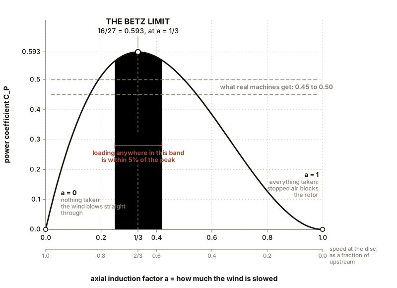
Read the two middle columns, because they say what the ideal machine physically does. At maximum power the rotor slows the wind to two thirds of its upstream speed at the disc, and to one third of it far downstream. Not to zero. Two thirds at the rotor, and no further, and any machine that tries to take more gets less.
And notice the flatness of that column. From a = 0.25 to a = 0.42, a range covering nearly a factor of two in how hard the machine is loaded, the power coefficient never falls below 0.56, which is 95 percent of the maximum. The peak is broad. That is a fact about the world that engineers should be grateful for daily: a turbine does not have to be operated precisely to be operated well, which is why a real machine with a real controller in real gusty wind can sit near its best point most of the time.
Section 4: One More Number, Free
The stream tube expansion promised in Section 1 costs nothing to extract now.
Mass conservation between the disc and the far wake says
ρ A u = ρ A₂ v₂. At the Betz condition, u is (2/3)v₁ and v₂
is (1/3)v₁, so
A₂ / A = u / v₂ = (2/3) / (1/3) = 2The far wake of an ideal turbine has exactly twice the area of the rotor, so its diameter is √2, or 1.41 times the rotor diameter. Upstream, the same argument gives an incoming stream tube of area (2/3)A, so 0.82 of the rotor diameter.
That is checkable, and it is checked constantly. Turbine wakes in fog and in sea spray are photographed regularly and they visibly expand. Chapter 9 uses this to explain why turbines in a farm are spaced five to nine rotor diameters apart, and Chapter 8 uses it to demolish a marketing claim.
And one more, for Chapter 12’s foundation designers. The thrust coefficient is
C_T = T / (½ ρ A v₁²) = 4a(1 − a)which at a = 1/3 is 8/9, or 0.889. An ideal rotor pushes backwards with almost ninety percent of the force that a solid disc of the same area would feel. For the 110 m (361 ft) rotor at 10.5 m/s (23 mph) that is a steady push of about 570 kN, or 128,000 lbf, applied 100 m (328 ft) up a steel tube. Chapter 12 explains what that does to the foundation, and Chapter 14 explains why reducing it is the main reason large machines pitch their blades.
Section 5: Where Real Machines Lose the Other Fourteen Percent
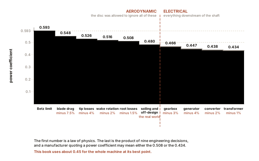
Betz says 0.593. A good modern rotor achieves an aerodynamic power coefficient of 0.47 to 0.50. Here is where the missing 0.10 to 0.12 goes, item by item, and every item is a thing the actuator disc was allowed to ignore.
Blade drag: about 7 percent of the total. Chapter 4 gave the estimate as λ divided by L/D. At λ of 7.5 and L/D of 100, that is 0.075. This is the largest single loss and it is why blade cleanliness and surface finish matter.
Tip losses: about 4 percent. A real rotor has a finite number of blades of finite length, so air spills around each tip from the high-pressure side to the low-pressure side, shedding a trailing vortex and doing no useful work. The actuator disc, being continuous, has no tips. This is the loss that gets worse as blade count falls, which is Chapter 6’s business.
Wake rotation: about 2 percent. A real rotor applies torque to the air, so by Newton’s third law the air leaves with a swirl, and that swirl carries away kinetic energy that no longer goes into the shaft. The faster the rotor spins for a given power, the less torque it applies and the less swirl it leaves, so this loss falls as tip-speed ratio rises, which is one of the two reasons a modern machine runs fast.
Root losses: about 1 to 2 percent. The inner section of the blade is thick, partly stalled and interrupted by the hub and nacelle, and contributes almost nothing.
Multiply through: 0.593 × 0.925 × 0.96 × 0.98 × 0.985 ≈ 0.508. Add manufacturing tolerance, blade soiling, imperfect twist and the fact that a machine spends most of its life away from its design point, and 0.45 to 0.48 is what a real rotor delivers on a good day.
Then, separately and afterwards, comes the electrical chain, and it is important not to muddle it in with the aerodynamics. Gearbox roughly 97 percent, generator roughly 96 percent, power converter roughly 98 percent, transformer roughly 99 percent, giving about 0.91 overall. So
wind to grid = 0.48 × 0.91 ≈ 0.44Which is the figure this book will use for the whole machine: an overall power coefficient of about 0.45 at the best point of the power curve. When a manufacturer quotes a Cp, always find out which of those two numbers they mean, because they differ by more than ten percent of themselves and a specification sheet does not always say.
ON THE BENCH: Watch the wind slow down
The Betz argument’s central claim is physical and measurable: air slows down before it reaches the rotor and keeps slowing afterwards. You can see it in an afternoon.
Parts: your winged rotor from Chapter 1 on its motor; a box fan; a cheap vane or hot-wire anemometer, $20 to $40; a tape measure; a load resistor of about 100 ohms and a switch; a stick to mount the anemometer on. Cost: the anemometer, if you do not own one. Time: an hour. Hazards: the fan. Do not hold the anemometer where a rotor blade can strike it.
Method: 1. Fix the rotor on a stand in the fan stream, at least 600 mm (24 in) from the fan so the jet has organised itself. 2. With the rotor removed, measure the air speed on the axis at five stations: 300 mm (12 in) upstream of where the rotor will be, 100 mm (4 in) upstream, at the rotor plane, 100 mm (4 in) downstream, and 600 mm (24 in) downstream. This is your baseline and it will not be flat, because a fan jet spreads. Write all five down. 3. Fit the rotor, open circuit so it spins freely and extracts almost nothing, and repeat all five measurements. 4. Now close the switch so the rotor drives the resistor and is genuinely loaded. Repeat all five measurements again.
What you should see: with the rotor loaded, the speed at the rotor plane is measurably lower than the baseline, and the speed 100 mm (4 in) upstream is lower too, which is the part that surprises people. The air knew the rotor was there before it arrived. Downstream, the deficit is larger than at the disc itself and it persists for a long way.
On a model rotor, expect the loaded speed at the disc to be perhaps 10 to 20 percent below baseline rather than the ideal 33 percent, because a card rotor is a light extractor. The direction of every effect is right and the magnitudes are small, exactly as Chapter 4 Section 6 warned.
If it does not work: if the upstream reduction is lost in the noise, take twenty readings at each station and average, or make the rotor a heavier extractor by lowering the load resistance until it visibly slows.
Better, if you have one: a smoke source upstream, and a phone on slow motion, will show the stream tube expanding around the loaded rotor. That is Section 4 made visible.
ON THE BENCH: Measure the thrust, and find the eight ninths
Section 4 says an ideal rotor pushes backwards with 8/9 of the force a solid disc would feel, and that this thrust rises and falls with how hard the rotor is loaded. Both halves are measurable with a hinge and a kitchen scale.
Parts: your rotor and motor; a light wooden or plastic arm about 400 mm (16 in) long with a free hinge at one end, so the rotor swings on it like a pendulum; a kitchen scale; a stiff wire pushing from the arm onto the scale pan; a box fan; a disc of card exactly the rotor’s diameter; a resistance box or a set of resistors; a multimeter. Cost: a few dollars. Time: an hour. Hazards: the fan. A hinged rotor can swing into the fan guard; fit a stop.
Method: 1. Zero the scale with the fan off, and check that the arm returns to the same place every time. 2. Solid disc first. Mount the card disc where the rotor will go and record the scale reading. That is your reference thrust, the force on a body that stops the air completely, and everything else is a fraction of it. 3. Replace the disc with the rotor, open circuit, so it spins fast and takes almost nothing. Record the thrust. 4. Now load the rotor progressively, from a high resistance down to a low one, recording thrust and electrical power at each step.
What you should see: three things, and the third is the one worth the hour.
First, the free-spinning rotor’s thrust is low, well under the disc’s, because a lightly loaded rotor barely disturbs the air. Second, as you load it the thrust rises and keeps rising even after the electrical power has peaked and started to fall. Third, and this is the finding: maximum power and maximum thrust do not occur at the same load. Past the power peak you are paying more and more force into the tower for less and less electricity.
That is the single most useful thing this box teaches, and it is why Chapter 13’s controller does not simply load the rotor as hard as it can, and why Chapter 12’s foundation is sized by an operating case rather than by the peak power case.
If it does not work: if the scale readings are lost in the noise, lengthen the arm to increase the moment, or use a cheap digital hanging scale on a string instead. Friction in the hinge is the usual culprit; a pin through two loose holes beats anything stiff.
Section 6: What the Limit Does and Does Not Say
Four clarifications, because all four are misquoted routinely, and Chapters 7 and 8 will need every one of them.
It is not an engineering limit and it will not be beaten by better engineering. It comes from conservation of mass and momentum applied to a permeable disc in an unbounded flow. There is no material, no geometry and no control strategy that gets around it, for the same reason no gearbox gets around conservation of energy.
It is a limit on the swept area, and the swept area is whatever the device occupies. This is the clause that does all the work in Chapter 8. If a rotor sits inside a shroud, the relevant area is the shroud’s frontal area, because that is the area of flow the device is interfering with. Quote a power coefficient against the small rotor instead and you can produce a number above 0.593 while having beaten nothing at all.
It applies to a device in a free stream, not in a pipe. A turbine in a duct with solid walls, a tidal turbine in a narrow channel, or a rotor in a wind tunnel with significant blockage all have different and higher limits, because the flow cannot escape sideways. That is a genuine and well-understood exception, it is why tidal stream turbines in constricted channels quote coefficients above 0.593 honestly, and it is not available to anything sitting in the open atmosphere.
And it says nothing whatever about whether a machine is worth building. Betz is a ceiling on capture per unit area. Cost per kilowatt-hour is a completely different quantity, and a device at 0.20 with a cheap structure can beat a device at 0.48 with an expensive one. Chapters 15 and 16 are about that, and Chapter 8’s bladeless mast makes exactly that argument and is entitled to.
SLOW DOWN. Check Your Understanding: The Betz limit says the ideal rotor slows the wind to two thirds of its upstream speed. A salesman tells you his rotor slows the wind to one quarter of its upstream speed at the disc, and offers this as evidence that it extracts more than a conventional machine. Is he right, and if not, what is actually happening? Answer before reading on.
He is wrong, and worse, he has described a machine that is extracting less than a good one.
Slowing the wind to a quarter at the disc means a = 0.75. Put that in the table: C_P = 4 × 0.75 × 0.0625 = 0.1875. He is capturing under a third of what the Betz-optimal machine captures.
The reason is the thing Chapter 1 promised and this chapter proved. Taking more velocity from each kilogram of air means fewer kilograms come through, because the air ahead has to go somewhere and it goes around. At a = 0.75 the wake velocity would be negative, which is physically impossible, so what actually happens is that the flow separates, the rotor behaves like a solid plate, and most of the air simply diverts around the disc without ever entering it. His machine is a very good parachute.
The general lesson is worth more than the arithmetic. Every intuitive measure of “taking a lot out of the wind” is the wrong measure. Big velocity deficit, loud noise, high thrust, visible turbulence: all of them can indicate a badly loaded rotor rather than a hard-working one. The only honest measure is power divided by ½ρAv³, with A being the frontal area of the whole device, and that number can never exceed 0.593.
Chapter 6 asks the question the actuator disc was forbidden to answer: given that we now know how hard to load the rotor, how many blades should it have and how fast should they go?

Bench Degree
Get the degree without the diploma.
Learn the material, not how to pass the exam.