Bench Degree·WIND POWERchapter
Chapter 4: Lift, and Why a Blade Is a Wing
A turbine blade in a 10.5 m/s (23 mph) breeze feels a 79 m/s (177 mph) wind. Not at the hub, at the tip, and the direction it comes from is nothing like the direction the wind is blowing. Get that one vector right and the whole machine explains itself.
Hold a dinner plate flat, edge-on to the wind, and it does nothing. Tilt it a few degrees and it tries to climb.
That is not the wind pushing it. The wind is going past almost parallel to the plate, and the force that appears is at right angles to the airflow, which is a direction the wind is not travelling in. Force perpendicular to the flow is called lift, and a force perpendicular to the flow is the only kind of force that can drive a blade faster than the air that is driving it. Chapter 1’s ribbon on the blade tip was a demonstration of that fact. This chapter is the mechanism.
Section 1: The Shape, Named
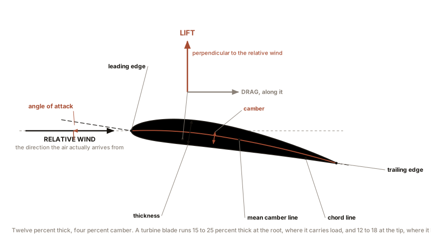
An airfoil is the cross-section of a blade, and it has five features worth naming because every specification uses them.
The leading edge is the rounded nose. The trailing edge is the sharp tail. The straight line between them is the chord, and its length is the chord length, written c. The curved line running from nose to tail midway between the upper and lower surfaces is the mean camber line, and how far it bows away from the chord is the camber. The thickness is the greatest distance between upper and lower surfaces, usually quoted as a percentage of chord.
A turbine blade is typically 15 to 25 percent thick near the root, where it must carry load, and 12 to 18 percent thick out toward the tip, where it must be efficient. Thick sections are strong and draggy. Thin sections are efficient and weak. The blade is a compromise that resolves differently at every station along its length, which is why it changes shape as it goes out.
And the angle that matters: the angle of attack, written α, is the angle between the chord line and the direction the air is actually arriving from. Not the direction the wind is blowing across the ground. The direction the air arrives from, as felt by the blade. Hold that distinction, because Section 4 is entirely about it.
Section 2: One Force, Resolved Two Ways
When air flows over an airfoil at a small angle of attack, the air passing over the upper surface is deflected and accelerated, its pressure falls, and the air below is decelerated slightly and its pressure rises. Both surfaces contribute. The net result is a single resultant force on the section.
That one force is conventionally split into two components, and the split is defined relative to the oncoming air:
Lift is the component perpendicular to the relative wind. Drag is the component parallel to the relative wind, in the direction of flow.
There is only one force. Lift and drag are two ways of describing it, chosen because the two components do completely different jobs on a rotor. Both are written the same way:
L = ½ ρ v² c C_L        (per unit length of blade)
D = ½ ρ v² c C_D
The same ½ ρ v² appears as in Chapter 1’s power
equation, because it is the same quantity: the dynamic
pressure of the moving air, the pressure it can exert by being
stopped. Multiply by the chord to get force per unit span, and by a
dimensionless coefficient that carries everything the shape and the
angle contribute.
Those coefficients are the whole of airfoil design and they
are measured, not calculated. Published airfoil data is a set
of curves of C_L and C_D against angle of
attack, at a stated Reynolds number, and Section 6 explains why that
last qualification is not a footnote.
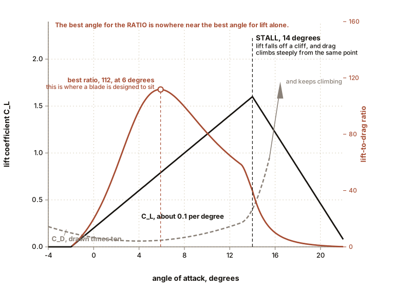
For a well-behaved airfoil at small angles, C_L rises
almost exactly linearly with angle of attack, at close to 0.1
per degree. So a section at 6 degrees has roughly twice the
lift coefficient of one at 3 degrees. This holds until it abruptly does
not.
Section 3: The Ratio That Is the Figure of Merit
Lift is what you want. Drag is what you pay. So the number that decides whether an airfoil is any good is the ratio of the two:
L/D = C_L / C_DLift-to-drag ratio is the figure of merit for a turbine blade, and it is not efficiency and it is not a percentage. It is a pure number, it depends on angle of attack, and every airfoil has one angle where it peaks.
The magnitudes, so you know what “good” means:
| Section | Best L/D |
|---|---|
| A flat plate at a few degrees | 5 to 10 |
| A cambered card blade, model scale | 10 to 20 |
| A model aircraft airfoil at model scale | 20 to 40 |
| A modern turbine airfoil at full scale | 100 to 150 |
| A high-performance sailplane wing | 40 to 60 (whole aircraft) |
That fourth row is the surprising one and it is not a misprint. A large turbine blade section running clean has a better lift-to-drag ratio than a sailplane’s whole wing, because it is thick, it operates at one design condition rather than across a flight envelope, and it does not have to carry a fuselage.
Why the ratio matters so much becomes clear in Chapter 6, but the shape of the answer is this: on a rotor running at tip-speed ratio λ, the fractional power lost to blade drag is roughly λ divided by L/D. At λ of 7.5 and L/D of 100, that is 7.5 percent of your power gone to drag. Halve the L/D to 50 and you lose 15 percent. Which is why a turbine blade’s surface finish is a performance item and why a layer of dead insects on the leading edge is worth money.
IN PLAIN ENGLISH: A blade is a lever that trades a small push into a large sideways force. Lift-to-drag ratio is how much of that trade you keep. At a hundred to one you are keeping nearly all of it. At ten to one, which is what a bent piece of card manages, you are keeping so little that a fast rotor is not worth building, and that is why nobody had a good wind turbine until they had good airfoils.
Section 4: The Vector That the Whole Chapter Exists For
Here is the piece that makes the rest of the book work.
A blade is moving. So the air it feels is not the wind, it is the vector sum of the wind and its own motion through the air. This is the same reason a cyclist on a still day feels a headwind.
Take a station on the blade at radius r, on a rotor turning at angular speed ω. Two velocities arrive at that station:
The axial component, which is the wind, slowed by
the rotor itself. Chapter 5 will prove that a good rotor slows the wind
to two thirds of its upstream speed at the disc, so call this
(2/3)v.
The tangential component, which is the blade’s own
speed through the air, ωr. This one points in the plane of
rotation, at right angles to the wind.
The relative wind that the section actually feels is the hypotenuse. Its magnitude is
W = sqrt( (2v/3)² + (ωr)² )and the angle it makes with the plane of rotation, called the inflow angle φ, is
φ = arctan( (2v/3) / (ωr) )Now put numbers in it, because the numbers are startling. Take the machine this book will use throughout: a rotor 110 m (361 ft) in diameter, so R is 55 m (180 ft), turning at 13.6 rpm in a wind of 10.5 m/s (23 mph). That is 1.43 radians per second, so the tip speed ωR is 78.5 m/s (176 mph).
At the tip: the axial component is 7 m/s (16 mph) and the tangential is 78.5 m/s (176 mph). So
- The relative wind speed W is about 79 m/s, which is 176 mph.
- The inflow angle φ is arctan(7 / 78.5), which is 5.1 degrees.
At a station one tenth of the way out, at r of 5.5 m (18 ft): the tangential speed is only 7.85 m/s (17.6 mph), the axial is still 7 m/s (16 mph), so
- W is about 10.5 m/s, or 23 mph.
- φ is arctan(7 / 7.85), which is 41.7 degrees.
Look at what that means. The air arrives at the root from 42 degrees away from where it arrives at the tip. If the blade were a straight untwisted plank, one end of it would be at a sensible angle of attack and the other end would be stalled or feathered uselessly.
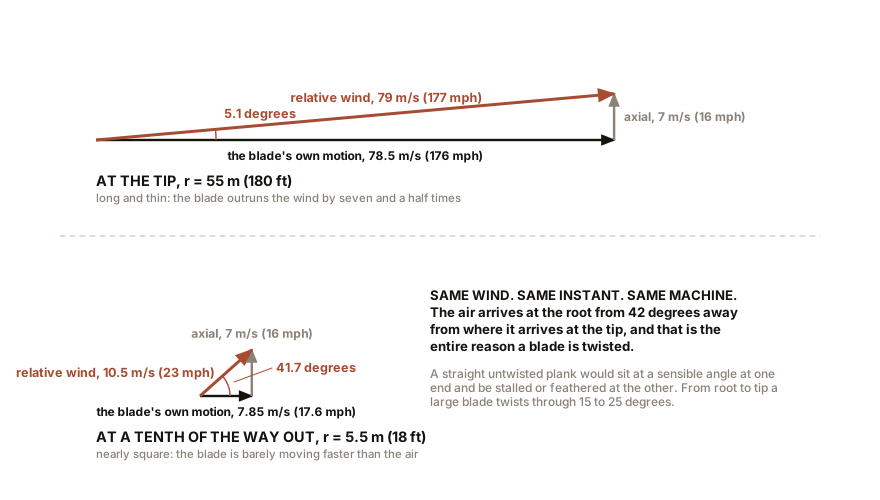
Which is the reason a turbine blade is twisted. The twist exists so that every station along the blade sits at roughly its own best angle of attack in the same operating condition. From root to tip a large blade twists through something like 15 to 25 degrees, and the direction of the twist follows directly from the arithmetic above.
IN PLAIN ENGLISH: A blade tip is going so much faster than the wind that the wind, from the tip’s point of view, is coming almost straight at it from the side. Near the hub, where the blade is barely moving, the wind is coming from nearly straight ahead. Those are two completely different flying conditions on the same piece of plastic, so the plastic has to be a different angle at each end.
And two more consequences fall out of the same arithmetic.
The tip does most of the work. Force per unit area goes as W squared, and W at the tip is nearly eight times W at the root, so the aerodynamic loading out there is over fifty times higher. Combine that with geometry: the outer third of the blade, from 67 percent of the radius to the tip, sweeps 55 percent of the total swept area. A little over half the area, carrying the highest loading, is why the outer third of a blade produces roughly two thirds of the torque, and why damage at the tip matters far more than damage at the root.
And this is why the tip speed is capped. Aerodynamic noise from a trailing edge rises roughly as the fifth power of the relative speed. Going from 78 m/s to 88 m/s (176 mph to 197 mph), a modest twelve percent, roughly doubles the acoustic power. Onshore machines are therefore held to about 75 to 80 m/s (168 to 179 mph) at the tip. Offshore, where nobody is listening, 90 to 100 m/s (201 to 224 mph) is used, and the machines are correspondingly cheaper for the same power.
Section 5: Stall, Which Here Is a Design Feature
Increase the angle of attack and the lift coefficient rises, linearly, satisfyingly, and then it collapses.
What has happened is that the boundary layer on the upper surface, the thin sheet of slowed air clinging to the skin, has run out of momentum against the rising pressure toward the trailing edge and separated. Instead of following the curve it detaches, leaving a broad wake of recirculating air. Lift falls, drag climbs steeply, and the section is stalled. For most airfoils this happens somewhere between 12 and 16 degrees.
In aviation stall is a hazard: it is the loss of the force holding the aircraft up. In a wind turbine, stall is a tool. Because a stalled section produces less lift, a blade that stalls as the wind rises limits its own power automatically, with no moving parts. That is Juul’s Gedser machine from Chapter 3, and it was the industry standard for thirty years. Chapter 14 sets stall regulation against pitch regulation properly.
Two related facts to carry:
Root stall is normal, all the time. At the innermost stations the inflow angle is over 40 degrees and no practical twist gets the whole blade to a clean angle. The inner fifteen percent of a large blade is usually partly separated in normal operation. It contributes little and it is there mainly as structure.
Stall is unsteady, and that is the problem with it. Separation does not arrive smoothly. A section going in and out of stall as the blade passes through wind shear, tower shadow and turbulence produces load fluctuations of several tens of percent at once per revolution, and Chapter 9 explains why that is a fatigue question and not a power question.
ON THE BENCH: A wind tunnel, and finding your own stall angle
Parts: a box fan; a cardboard box big enough to make a duct about 300 mm (12 in) square and 600 mm (24 in) long; drinking straws or a section of plastic honeycomb to straighten the flow; a wing section 100 mm (4 in) in chord and 200 mm (8 in) in span, carved from foam or laminated from card over a former; a length of 3 mm (0.12 in) dowel through the section as a pivot; a kitchen scale; a protractor; a stiff wire arm; incense or a smoke pen. Cost: about $20, less if the fan and scale are already yours. Time: an evening to build, an hour to run. Hazards: the fan blades. Do not put fingers in the intake. Incense is a fire source; keep it away from the cardboard and away from foam.
Method: 1. Build the duct as a plain open-ended box in front of the fan, with a bundle of straws across the inlet to break up the swirl. The flow will not be uniform and that is acceptable; you need repeatability, not calibration. 2. Mount the wing on its pivot across the duct, with the wire arm sticking out through a slot and resting on the kitchen scale so that lift pushes down on the pan. Zero the scale with the fan off. 3. Set the angle of attack with the protractor. Run the fan. Record the scale reading. 4. Step the angle from 0 to 20 degrees in 2-degree steps. Record every reading, going up and then coming back down.
What you should see: the reading rises nearly in a straight line, then flattens, then falls, somewhere between 10 and 16 degrees. That is your stall angle, measured. Coming back down, the reading is often lower than it was on the way up at the same angle: separated flow does not reattach at the angle where it separated. That is hysteresis and it is real, and it is one of the reasons stall-regulated machines are hard to control precisely.
If it does not work: if the readings are noisy, the flow is too turbulent. Move the wing further from the fan, lengthen the duct, or add a second straw bundle. If nothing registers, the section is too small; double the span.
Better, if you have one: hold a smouldering incense stick upstream and watch the smoke line. Below stall it follows the curve of the upper surface. At stall it lifts off and breaks up, and you can see the separation point walk forward as you increase the angle. Seeing separation is worth more than measuring it.
ON THE BENCH: Measure the inflow angle, and derive your own twist
Section 4 claims the air arrives at the root from 42 degrees away from where it arrives at the tip. That is not a claim you have to take on trust, and confirming it is the most satisfying measurement in this chapter.
Parts: your three-blade winged rotor and motor; a box fan; three short lengths of fine sewing thread; three dressmaker’s pins or fine wire staples; a phone with a camera; a printed protractor or a protractor app. Cost: nothing. Time: 45 minutes. Hazards: the fan. Push the pins in from the trailing edge so nothing sharp faces forward, and check the rotor is still balanced afterwards.
Method: 1. Fix a pin to one blade at each of three stations: near the root, at the middle, and near the tip. Tie a 30 mm (1.2 in) length of thread to each pin so it can pivot freely. Each thread is now a tiny wind vane that will lie along the relative wind at its own station. 2. Run the rotor up to speed in the fan. Photograph the blade from directly along the rotor axis, using the shortest exposure your phone allows, or better, a burst of stills. 3. In the photographs, measure the angle each thread makes with the plane of rotation. 4. Predict those three angles first. Measure the rotational speed, compute the tangential speed at each station as ω times r, take the fan’s air speed as the axial component, and compute the inflow angle as the arctangent of the ratio.
What you should see: three visibly different angles, small at the tip and large at the root, and predictions that land within a few degrees of what you measured. You have now measured the vector that Section 4 exists to deliver, on a cork, with three pieces of thread.
If it does not work: if the threads all trail straight back, they are too long and too heavy and centrifugal force is dominating. Use finer thread and make them shorter. If the photos are unreadable, light the rotor from the side with a bright lamp and shorten the exposure further.
Better, if you have one: repeat at two fan speeds. The tip angle will change less than the root angle, because at the tip the tangential term dominates the arctangent and at the root it does not. That is why the outer part of a blade needs little pitch adjustment across the whole operating range and the inner part is permanently compromised, which is Chapter 13’s Region 3 seen from the blade’s point of view.
Section 6: What the Bench Cannot Give You, and Why
This is where the series is obliged to be honest with you, and the honesty is quantitative.
The behaviour of an airfoil depends on a dimensionless quantity called the Reynolds number, which is the ratio of inertial to viscous forces in the flow:
Re = W c / νwhere W is the relative wind speed, c is the chord, and ν is the kinematic viscosity of air, about 1.5 × 10⁻⁵ square metres per second.
Now compare your bench with a real machine.
Your wing section in the duct above: W of maybe 5 m/s (11 mph), chord of 0.1 m (4 in). That gives a Reynolds number of about 33,000.
The tip of the 110 m (361 ft) rotor: W of 79 m/s (177 mph), chord of about 1.5 m (59 in). That gives about 7.9 million.
A factor of two hundred and forty. And Reynolds number is not a cosmetic parameter. At the low end the boundary layer is laminar, thick, and separates easily. At the high end it is turbulent, thin, and clings. The consequences are direct: your card blade will reach an L/D of perhaps 15, and the real blade reaches 120. Your section will stall earlier and more gently. Your rotor will never approach the power coefficient of a full-scale machine no matter how carefully you shape it.
So state the limit plainly. A model rotor demonstrates every mechanism in this book and predicts the performance of none of them. You can measure that lift is perpendicular to the flow, that stall exists, that twist is necessary, that three blades beat sixteen, that power goes as the cube of speed and the square of diameter, and that shrouding a rotor does not beat Betz. Every one of those is a matter of principle and every one of them shows up at model scale.
What will not show up is the absolute number. When your rotor reaches a power coefficient of 0.20 and the book says a real machine reaches 0.47, the difference is Reynolds number and not your workmanship.
SLOW DOWN. Check Your Understanding: A large turbine blade’s chord is widest at about a quarter of the way out from the hub and tapers steadily to a narrow tip. Given that Section 4 showed the tip does most of the work, why is the blade narrowest exactly where the work is being done? Answer before reading on.
Because force per unit area goes as the square of the relative wind speed, and the relative wind speed at the tip is nearly eight times what it is near the root. The tip needs very little area to produce a large force. The root needs a great deal of area to produce a small one.
Run the arithmetic on the aerodynamic requirement and the ideal chord falls off roughly as one over radius. A blade shaped strictly to that rule would be absurdly wide at the hub, so real blades compromise: they taper from a maximum at around 20 to 25 percent of radius, and inboard of that they stop trying to be aerodynamic and become structure, because the root has to carry the bending moment of the entire blade.
The blade is therefore two different objects sharing a skin. The outer two thirds is a wing optimised for lift-to-drag. The inner third is a cantilever beam optimised for stiffness, mass and the bolted joint at its end, and the fact that it is shaped like an airfoil at all is nearly decoration. Chapter 11 builds it.
Chapter 5 now takes the whole rotor rather than one section of one blade, and asks the question Betz asked: given that the machine must let the air keep moving in order to let more air arrive, what is the most it can possibly take?

Bench Degree
Get the degree without the diploma.
Learn the material, not how to pass the exam.