Bench Degree·WIND POWERchapter

Chapter 6: Tip-Speed Ratio and Blade Count
Everybody asks why there are three blades. Almost nobody asks the question underneath it, which is why the blades are going seven times faster than the wind. Answer the second and the first answers itself.
There is one number that a rotor designer chooses before choosing anything else, and every subsequent decision falls out of it. It is not the diameter, it is not the blade count and it is not the airfoil.
It is the ratio of the blade tip’s speed to the wind’s speed.
λ = (tip speed) / (wind speed) = ωR / vThe Greek letter lambda, pronounced “lambda”, and always called tip-speed ratio. It is dimensionless, which is why you can measure it on a 300 mm (12 in) card rotor in your kitchen and compare the answer directly with a 110 m (361 ft) machine on a hill, and the comparison is meaningful.
Chapter 1 asked you to measure it with a ribbon and a stopwatch. Here is what the answers mean.
Section 1: The Numbers, Measured
| Machine | Typical λ | Typical peak C_P |
|---|---|---|
| Persian panemone, Chapter 2 | 0.2 to 0.5 | 0.05 to 0.12 |
| Savonius rotor | 0.8 to 1.0 | 0.15 to 0.20 |
| American farm windmill | 0.8 to 1.2 | 0.20 to 0.30 |
| Charles Brush, 1888 | about 1 | perhaps 0.08 |
| Dutch four-sail tower mill | 2 to 3 | 0.15 to 0.20 |
| Darrieus, vertical axis lift machine | 4 to 6 | 0.35 to 0.40 |
| Modern three-blade turbine | 7 to 9 | 0.45 to 0.50 |
| Two-blade turbine | 9 to 12 | 0.45 to 0.50 |
Read down the two right-hand columns together, because they move together. Every machine in the top half of that table is slow and takes little. Every machine in the bottom half is fast and takes a lot. The correlation is not a coincidence and it is not quite a cause either, and untangling it is the work of this chapter.
Note also that the correlation does not continue forever. Going from three blades at λ of 8 to two blades at λ of 11 buys no extra power coefficient at all. The curve has flattened. That will matter in Section 4.
Section 2: Why Fast Is Better, and Where It Stops
Three reasons to run fast, and two reasons not to, and the optimum sits where they balance.
Fast reason one: wake swirl. A rotor extracts power
by applying torque to the air, and the air leaves with a swirl that
carries away kinetic energy the shaft never sees. For a given power,
torque and rotational speed trade off inversely: P = Tω. So
a fast rotor needs less torque for the same power, imparts less swirl,
and loses less. The loss is severe at low λ and negligible above about
6. This is the single largest reason a slow rotor cannot reach a
high power coefficient, and it is why the top half of the table
is stuck where it is.
Fast reason two: torque is expensive. Take the machine this book uses: 3.26 MW of aerodynamic power at 10.5 m/s (23 mph) on a 110 m (361 ft) rotor. At λ of 7.5 the rotor turns at 13.6 rpm, and the shaft torque is about 2.3 MN·m, or 1.7 million lb·ft. Now imagine the same machine designed for λ of 3. The rotor turns at 5.5 rpm and the torque rises to 5.7 MN·m, two and a half times as much. Shafts, bearings, gearbox housings and hub castings are sized by torque, so halving the speed roughly doubles the weight and cost of the drivetrain to deliver the same electricity. Speed is the cheapest thing in a rotor.
Fast reason three: less blade. A fast blade generates a lot of lift from a small chord, because Chapter 4 showed the force goes as the relative wind speed squared. Fast rotors are therefore slender, which means less material, less mass and less to lift up a tower.
Slow reason one: drag. Chapter 4 gave the estimate: the fraction of power lost to blade drag is roughly λ divided by the lift-to-drag ratio. So drag loss rises in direct proportion to λ. At λ of 7.5 with L/D of 100 you lose 7.5 percent. At λ of 15 you lose 15 percent, and at λ of 30 there is nothing left. The lift-to-drag ratio of your airfoil is what sets the ceiling on tip-speed ratio, and this is why good airfoils and fast rotors arrived together historically. La Cour could not have built a λ of 8 machine out of canvas.
Slow reason two: noise and erosion, and both go as high powers of speed. Aerodynamic noise from a trailing edge rises roughly as the fifth power of the relative velocity. And rain, hail and grit strike the leading edge at that velocity, so erosion damage climbs even faster. Onshore machines are held to about 75 to 80 m/s (168 to 179 mph) at the tip essentially by planning permission. Offshore, out of earshot, 90 to 100 m/s (201 to 224 mph) is normal.
IN PLAIN ENGLISH: A slow rotor wastes energy by stirring the air into a spiral, and it needs a huge expensive shaft. A fast rotor wastes energy by dragging its blades edgewise through the air, and it screams. The best design is as fast as its blades will let it be before drag and noise take back what speed gained.
Section 3: The Optimum, and Why It Depends on Blade Count
Now the connection between λ and blade count, which is the part that is usually asserted rather than explained.
A blade leaves a mess behind it. Each blade sheds a wake of disturbed, slowed, swirling air. The next blade around should ideally arrive after that mess has swept downstream and out of the way, into air that has not been used yet.
How long does that take? The disturbed air moves downstream at
roughly the wind speed. The time until the next blade arrives at the
same azimuth is 2π / (nω), where n is the blade count. Set
the second roughly equal to the first, at a distance of order the blade
chord, and the algebra gives a result whose form is the useful
part:
The optimal tip-speed ratio falls roughly as one over the blade count. Fewer blades means each one must go faster to sweep the same air in the same time. More blades means each can go slower.
The classic rule of thumb states this as
λ_opt ≈ 4π / nwhich gives 12.6 for one blade, 6.3 for two, 4.2 for three and 2.1 for six.
Now be careful, because that formula is quoted far more confidently than it deserves. Compare its prediction of 4.2 for a three-blade rotor with the 7 to 9 that real three-blade machines actually run at. The rule is wrong by a factor of two.
The reason is that the derivation implicitly assumes a rotor whose losses are dominated by wake effects, which is true when the blades are draggy. Once L/D reaches 100 or more, drag loss is small even at high λ, and the optimum shifts a long way upward. So the rule gets the trend right and the magnitude wrong, and that is exactly how it should be used: as a statement that halving the blade count roughly doubles the design speed, not as a design tool.
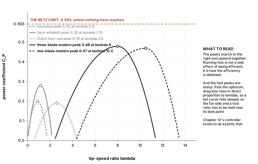
That last observation in the caption is worth stating outright. A fast rotor has a sharper peak than a slow one. The Savonius produces something across a wide range of speeds. The three-blade machine has a pronounced maximum and falls off steeply on both sides of it, and above the peak it falls off very steeply indeed as drag takes over. Which means a fast machine has to be operated at the right speed or it is not a fast machine, and that is the entire reason variable-speed control exists. Chapter 13 is that story.
Section 4: Why Three
Four arguments, in ascending order of how much they actually decide the matter.
Argument one, capture, which decides very little. Going from two blades to three raises the peak power coefficient by perhaps 1 to 3 percent. Going from three to four raises it by well under 1 percent. Beyond three, additional blades buy essentially nothing, because a rotor at λ of 8 with three blades is already sweeping the disc thoroughly. The capture argument is real, it explains why one blade is a bad idea, and it does not distinguish three from four.
Argument two, cost, which decides against four and five. Blades and hub are roughly 20 percent of a turbine’s capital cost. A fourth blade adds a third to that, so 6 or 7 percent to the machine, for under 1 percent more energy. It also adds mass at the top of the tower, which the tower and foundation must carry. Four blades is a straightforward economic loss and always has been.
Argument three, cyclic loading, which is the one that decides against two. This is the argument most often given badly, so here it is properly.
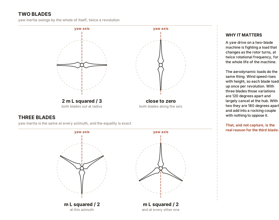
A rotor with two blades has a moment of inertia about the yaw axis, the vertical axis of the tower, that changes as it rotates. With the blades horizontal the rotor is a long bar and its yaw inertia is large. A quarter turn later, blades vertical, the rotor is nearly a point mass and its yaw inertia is small. That variation happens twice per revolution, and if the nacelle yaws or the tower sways while it happens, energy pumps back and forth between the rotation and the structure in a way that generates large cyclic loads.
With three or more blades, that variation vanishes entirely. Three or more equally spaced masses distribute their second moment isotropically in the plane, so the rotor’s yaw inertia is exactly the same at every azimuth. Not approximately the same. Exactly.
The same isotropy applies to the aerodynamic loads. Wind speed rises with height, so the blade at the top of its circle always sees more wind than the blade at the bottom, and each blade therefore produces a load that varies once per revolution. With three blades, the three variations are 120 degrees out of phase and largely cancel when summed at the hub. With two blades they are 180 degrees out of phase, which is to say they add into a pure rocking couple with nothing to oppose it.
Two-blade machines can be built, and the standard fix is a teetering hub, a pivot that lets the rotor rock like a see-saw so the imbalance is not transmitted into the shaft. That works, and it adds a large, heavily loaded, safety-critical hinge to the most inaccessible part of the machine. Three blades cost a blade. Two blades cost a hinge. The industry has repeatedly decided the blade is cheaper, and the two-blade concept keeps returning for offshore use, where noise limits are relaxed and installation cost dominates, and keeps failing to displace three.
Argument four, which is not physics at all and matters anyway. A two-blade rotor at λ of 11 is noisier than a three-blade rotor at λ of 8, by the fifth-power law of Section 2. And a two-blade rotor is perceived by observers as visually restless, because a two-blade disc genuinely does look different in each half revolution while a three-blade one does not. Planning objections are a real engineering constraint. A machine that cannot be permitted has a power coefficient of zero.
ON THE BENCH: Two, three and six blades, and the trade you cannot dodge
This is the definitive blade-count experiment and it takes an afternoon. Everything in Section 4 shows up except the teeter argument, which needs a real machine.
Parts: one hub that accepts blades in interchangeable sockets, made from a wine cork drilled with six evenly spaced radial holes; six identical blades of 3 mm (0.12 in) plywood or stiff card, each about 130 mm (5 in) long, cambered and twisted so the tip sits about 8 degrees and the root about 25 degrees from the plane of rotation; your hobby motor; a box fan; a multimeter; a 100 ohm resistor; a photo tachometer or a phone camera on slow motion; thread, a small paper cup, and coins. Cost: under $10 beyond Chapter 1’s kit. Time: three hours including making six matched blades. Hazards: the fan intake. Any rotor with unevenly spaced blades will shake violently; only ever fit blades in symmetric patterns, so two blades opposite each other, three at 120 degrees, or all six.
Method. For each of two, three and six blades, at one fixed fan setting and one fixed distance, record four things: 1. Open-circuit voltage, as a proxy for speed. 2. Voltage across the 100 ohm resistor, from which power is voltage squared over resistance. 3. Rotational speed, from the tachometer or by counting frames. 4. Starting torque, by the thread-and-coins method of Chapter 2: the largest mass the rotor will lift from a dead stop.
Then compute tip-speed ratio for each configuration. You need the fan’s air speed once, from an anemometer or by timing a tissue scrap across a measured distance.
What you should see, and predict each before you measure it:
- Six blades: the slowest rotor and the highest starting torque, by a wide margin. It will start under a load that the two-blade rotor cannot budge. Its λ will be low, around 2 to 3.
- Two blades: the fastest rotor and almost no starting torque. It may need a flick to get going at all. Its λ will be the highest of the three.
- Three blades: the most power into the resistor, and a λ in between. This is the result the whole industry converged on, reproduced on a cork.
If it does not work: if six blades produce more power than three, your blades are too draggy, which at card-scale Reynolds numbers is entirely possible. Chapter 4 Section 6 explains why, and the fix is a smoother, thinner, better-cambered blade rather than more of them.
Better, if you have one: a variable load, meaning a potentiometer instead of a fixed resistor, lets you sweep the electrical load at fixed wind speed and plot power against rotational speed. That curve is the power coefficient against tip-speed ratio curve of Figure ch06-cp-lambda, measured by you, and there is no substitute for having drawn it yourself.
ON THE BENCH: Hear the fifth power
Section 2 claims aerodynamic noise rises as roughly the fifth power of tip speed. That is a large claim about a steep law and it is testable in twenty minutes with a phone.
Parts: your three-blade rotor; a box fan with at least two speeds; a phone with a sound level meter application, free ones are adequate for a difference measurement; a tachometer or a phone on slow motion; a quiet room, late in the evening. Cost: nothing. Time: 30 minutes. Hazards: the fan. And do not do this at two in the morning if you have neighbours, which is itself Section 4’s fourth argument in miniature.
Method: 1. This measurement’s enemy is the fan’s own noise, which will swamp the rotor’s. So the rotor must be driven by something quiet. Drive it as a fan instead, by connecting the hobby motor to a variable bench supply or a battery and a potentiometer, and run the rotor as a propeller in still air with the box fan switched off entirely. 2. Fix the phone at a set distance, 500 mm (20 in) is convenient, on the rotor’s axis. Record the background level with the rotor stopped. 3. Run the rotor at a low speed. Record the rotational speed and the sound level. 4. Raise the speed to roughly one and a half times the first, and record both again.
What you should see: the prediction is that the sound level rises by 50 times the base-ten logarithm of the speed ratio. For a speed ratio of 1.5 that is 8.8 decibels. For a ratio of 2.0 it is 15 decibels.
Fifteen decibels is not a subtle difference. It is roughly the difference between a quiet office and a conversation, and it is the entire reason onshore turbines are held to a tip speed of 80 m/s (179 mph) while offshore machines run at 100 m/s (224 mph) and are cheaper for it.
If it does not work: you will very likely measure less than the predicted rise, and the reason is almost certainly that the background level is close to your readings. Subtract levels properly rather than arithmetically, or move somewhere quieter. Motor noise also does not obey the fifth-power law, so a noisy motor will flatten the result; a geared-down quiet motor helps.
What this box cannot show you is the character of the sound, which is what people actually object to. A large turbine’s noise is dominated by trailing-edge broadband hiss with a once-per-blade-pass amplitude modulation, and it is that rhythmic swish rather than the loudness that generates complaints. A number in decibels has never settled a planning dispute.
Section 5: Solidity, and Two Correct Answers to the Same Question
Solidity is the fraction of the swept disc that is actually blade:
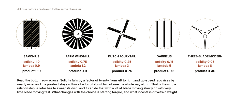
σ = (total blade planform area) / (swept area)The numbers span more than an order of magnitude:
| Machine | Blades | Solidity |
|---|---|---|
| Modern three-blade turbine | 3 | about 0.05 |
| Darrieus | 2 or 3 | 0.10 to 0.25 |
| Dutch tower mill | 4 | 0.20 to 0.30 |
| American farm windmill | 15 to 24 | 0.70 to 0.80 |
| Savonius | 2 | effectively 1.0 |
Solidity and tip-speed ratio are two views of the same choice, related roughly by σ × λ being of order one. A rotor must sweep the whole disc in the time it takes air to cross it, and it can do that with a lot of blade going slowly or a little blade going fast.
Which brings the chapter to the place it has been heading since Chapter 2.
A farm water pump and a power turbine are the same physics arriving at opposite answers, because the loads are different objects.
The pump has to break a standing column of water out of a well, from rest, unattended. What it needs is torque at zero speed. Torque at zero speed is what solidity buys: at a standstill every blade sits at a large angle of attack and contributes a push, and twenty blades push twenty times as hard as one. The starting torque coefficient of a farm windmill is of the order of 0.5. For a three-blade power turbine it is of the order of 0.02.
That is a factor of about twenty-five, and it is the whole story. The farm windmill starts under load in a 3 m/s (7 mph) breeze against a full riser. The power turbine, at rest, in the same breeze, does nothing at all: its blades are stalled, it has almost no solidity, and it cannot begin. Which is fine, because its load is a generator whose torque can be commanded to zero while the rotor spins up, and then applied. The turbine gets to choose when its load arrives. The pump does not.
Both machines are correct. Neither would survive the other’s job for an afternoon.
SLOW DOWN. Check Your Understanding: A one-bladed turbine sounds absurd, and several have been built and run, including megawatt-scale machines in Germany and Italy in the 1980s and 1990s. Given everything in this chapter, name the one real advantage a single blade has, and then name the reason it lost anyway. Answer both before reading on.
The advantage is cost, and specifically the cost of the thing that matters most. Blades are the expensive, fatigue-critical, transport-limited component. One blade with a counterweight is genuinely cheaper than three, and because Section 3 says the optimum tip-speed ratio scales as one over blade count, a single blade can run at λ of 15 or more and still sweep the disc adequately. The peak power coefficient of a well-built one-blade rotor is only a few percent below a three-blade machine’s. On paper it is close to a free lunch.
It lost on the fifth power of tip speed, and on the cyclic loading argument taken to its extreme.
Running at λ of 15 rather than 8 nearly doubles the tip speed, and noise goes as roughly the fifth power, so the acoustic power goes up by a factor of about thirty. That alone would end it onshore.
And the cyclic loading is not merely worse than a two-blade rotor’s, it is a different category of problem. One blade plus a counterweight is mass-balanced but not aerodynamically balanced: the lift is produced on one side of the hub only, once per revolution, forever. Every load path in the machine sees a full reversal each turn, twenty times a minute, twenty million times a decade. Chapter 9 shows that fatigue damage in a composite goes roughly as the tenth power of stress range, so a design that doubles the alternating load does not double the damage, it multiplies it by about a thousand.
The general lesson: a rotor is not judged on its power coefficient. It is judged on cost per unit of energy delivered over twenty years, and fatigue is what sets the twenty years. That is a sentence to keep for Chapters 7 and 8, where several designs with respectable power coefficients turn out to be poor machines, and one design with a terrible power coefficient turns out to have an argument.
Chapters 7 and 8 now take the two tools this chapter and Chapter 5 have built, which are lift beats drag and Betz applies to the whole frontal area, and point them at six configurations that are all currently for sale.

Bench Degree
Get the degree without the diploma.
Learn the material, not how to pass the exam.