Bench Degree·WIND POWERchapter
Chapter 7: Four Ways to Take Wind
You now own two tools. Lift beats drag, and Betz applies to the whole frontal area. Everything for sale in this field can be judged with those two sentences, and this chapter judges it.
Six configurations are currently manufactured and sold as wind machines, and there is a seventh that nobody counts because it does not move. This chapter takes the four that turn a shaft, and Chapter 8 takes the other three.
This is not a list to memorise. Chapters 4 to 6 gave you the means to predict how each one performs before anybody tells you, and the exercise of this chapter is to make the prediction first and then check it. Two rules do almost all of the work.
Rule one: lift beats drag, and the margin is a factor of four. Section 2 derives that factor rather than asserting it.
Rule two: the Betz limit applies to the total frontal area of the device. Not to the rotor inside it. Not to the part that turns. To the whole area of moving air the thing interferes with. Chapter 8 Section 1 is where that rule earns its keep.
A third rule, quieter than the others and eventually the important one: a power coefficient is not a verdict. Cost per kilowatt-hour delivered over twenty years is the verdict, and one of the machines in these two chapters has a poor power coefficient and a serious argument.
Section 1: The Benchmark
The three-blade horizontal axis machine, upwind of its tower, is the shape everybody pictures and it is the one to beat. Chapter 6 explained every part of it: three blades for isotropic loading, tip-speed ratio of 7 to 9, solidity around 5 percent, aerodynamic power coefficient of 0.45 to 0.50 and an overall wind-to-grid figure near 0.45.
It is a direct descendant of Charles Brush’s machine of 1888, and the descent is instructive because of what got thrown away. Brush had 144 cedar blades on a 17 m (56 ft) rotor, because in 1888 nobody knew about tip-speed ratio and the obvious way to catch more wind was to put more wood in the way. The modern machine has three blades, twenty times the diameter, and takes roughly six times the fraction of the wind. Everything gained between 1888 and now was gained by taking blades off.
Every other configuration in this chapter is a departure from that benchmark, and each departure is made to buy something: direction insensitivity, starting torque, low noise, small footprint, turbulence tolerance, or the absence of anything that can wear out. In every case the currency is capture. The question is never whether a design gives up efficiency. It always does. The question is what it gets for it, and whether the reader needs that thing.
Section 2: The Savonius, and the Ceiling on Being Pushed
Sigurd Johannes Savonius, a Finnish engineer, filed on 13 August 1925 and was granted US patent 1,697,574 on 1 January 1929, titled Rotor adapted to be driven by wind or flowing water. His own words for the shape are “two oppositely arranged hollow shaped vanes”, overlapping to leave an S-shaped passage through the middle, which is the detail most reproductions leave out. It is two half-cylinders, like an oil drum cut lengthways, offset on a vertical shaft so that one scoop presents its open face to the wind while the other presents its back.
It is a drag device. The wind pushes it. So Chapter 4 predicts it will be poor, and the prediction can be made exact.
Here is the ceiling on any drag machine, and the derivation is four lines.
Take a plate of area A with drag coefficient C_D, moving downwind at
speed u in a wind of speed v. The wind it feels is only
v − u, because it is running away. So the drag force on it
is
F = ½ ρ C_D A (v − u)²and the power it delivers is that force times the speed at which it retreats:
P = F u = ½ ρ C_D A (v − u)² uDivide by the wind’s power to get a power coefficient, and write
x = u/v:
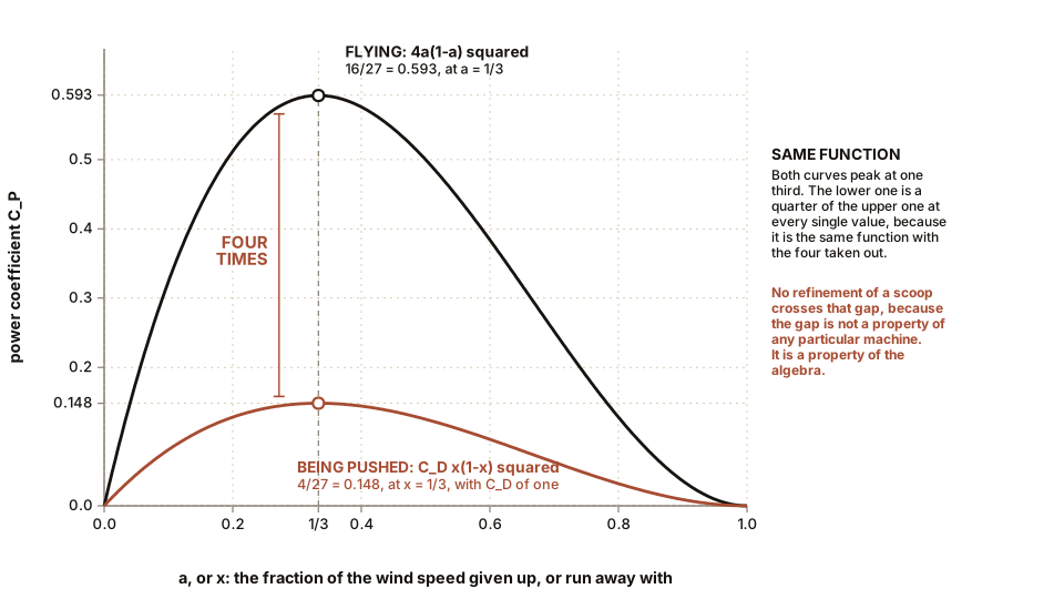
C_P = C_D · x (1 − x)²Look at that expression, because you have seen it
before. It is exactly Chapter 5’s 4a(1−a)² with
the four removed and a drag coefficient bolted on. Same function, same
maximum location: x = 1/3, meaning the plate travels at one third of the
wind speed. And the value there is
C_P,max = C_D × (1/3)(2/3)² = 4 C_D / 27For a plate with a drag coefficient of one, that is 4/27, which is 14.8 percent. Betz’s ideal lift machine gets 16/27. The drag machine’s ceiling is exactly one quarter of the lift machine’s, and the four comes out of the same algebra. That is the factor this chapter’s first rule promised, derived rather than quoted.
Now the honesty. A real Savonius does better than 4/27. Careful wind tunnel work, including a well-known series of tests at Sandia National Laboratories in the 1970s that covered two-bucket and three-bucket rotors across a range of overlap ratios, put the best measured power coefficients at around 0.20 to 0.25, at a tip-speed ratio near 0.9. So how does it beat its own ceiling?
Three ways, all legitimate and none of them large. The concave scoop has a drag coefficient of well over one while the convex back has one of around 0.3, so the net is better than a single plate. The gap between the two scoops lets air pass from the advancing side across to the inside of the returning scoop, which pushes it along instead of holding it back. And at some azimuths a curved scoop develops a little genuine lift.
So the correct statement is that a Savonius sits at 0.20 or so against a good horizontal machine’s 0.47, which is less than half, and that it will never approach the benchmark because pushing is worth a quarter of flying and no amount of scoop refinement changes the category.
What it buys is worth naming, because it is real. Enormous starting torque, so it turns under load in the lightest breeze. Complete indifference to wind direction, so no tail, no yaw drive, no wiring twist. A tip speed near the wind speed, so it is almost silent and it does not chop anything. Tolerance of turbulent, swirling, direction-reversing air of the kind found between buildings. And a construction that a competent amateur can build from a drum, a shaft and two bearings.
Those are the specifications of a good water pump, a good ventilator and a good battery trickle charger. They are not the specifications of a generating station, and a Savonius sold as one is being sold dishonestly.
Section 3: The Darrieus, Which Flies and Cannot Start
Georges Jean Marie Darrieus, a French engineer in Paris, filed on 1 October 1926 and was granted US patent 1,835,018 on 8 December 1931, titled Turbine having its rotating shaft transverse to the flow of the current. The machine that looks like an eggbeater: two or three slender airfoil blades bowed outward from a vertical shaft. The patent states the point of it plainly, that the blades can run faster than the current itself, which is the whole difference between this and a Savonius.
This is a genuine lift device on a vertical axis, so it is not subject to the drag penalty at all. The blades whip around the axis at three to six times the wind speed, and at any instant each one is flying, exactly as a horizontal machine’s blade flies. Measured power coefficients on large research machines, including the 17 m (56 ft) and 34 m (112 ft) test beds that Sandia National Laboratories ran in New Mexico and in Texas from the late 1970s into the 1990s, reach 0.35 to 0.40.
That is a serious number. It is not 0.47, and the shortfall has two causes that are inherent to putting the axis vertical and cannot be engineered away.
Cause one: the angle of attack cycles continuously. A horizontal machine’s blade sits at nearly the same angle of attack all the way round. A vertical machine’s blade sweeps through the full range twice per revolution, from positive through zero to negative and back, so it is at its best angle for only a fraction of each turn and it passes through or near stall twice.
Cause two: half the circle is in the machine’s own wake. The downwind half of the rotor runs in air that the upwind half has already used and slowed. There is no arrangement of blades that avoids this, because it is a consequence of the axis being perpendicular to the flow.
The bowed shape, incidentally, is one of the loveliest pieces of engineering in this book. It is called a troposkein, the curve a flexible rope takes when spun about its ends, and a blade formed to that curve carries its own centrifugal load in pure tension with no bending at all. Chapter 11’s horizontal blade is a cantilever fighting a bending moment for its whole life. The Darrieus blade simply hangs.
And then the defect, which is famous and which you can now derive. A Darrieus at rest cannot start. At zero rotational speed the blade’s relative wind is just the wind, so its angle of attack is set purely by where it happens to be standing, and around most of the circle that angle is far past stall. Averaged over a revolution the torque is close to zero and can be negative. The machine has a dead band from a standstill up to a tip-speed ratio of roughly one or two, and it has to be pushed through it.
The usual fixes are to motor it up using the generator, or to bolt a small Savonius rotor onto the same shaft purely as a starter, which is a pleasing admission: the drag machine is a poor generator and an excellent starter motor, exactly as Chapter 6’s solidity argument says it should be.
The other Darrieus problem is fatigue. Because torque varies twice per revolution with an amplitude comparable to the mean, and sometimes goes negative, every joint in the machine sees a full load reversal at twice rotational frequency for its entire life. Chapter 9’s tenth-power fatigue rule makes that expensive. Elegant and temperamental is a fair summary.
ON THE BENCH: Savonius against Darrieus, on the same shaft
This is the chapter’s central experiment and the result is a refusal, which is the point.
Parts: a Savonius rotor from a 110 mm (4.3 in) drain pipe or a plastic drum cut lengthways, about 400 mm (16 in) tall; a straight-bladed Darrieus of the same swept area, made from three lengths of aluminium angle or three cambered card blades on top and bottom spokes, about 300 mm (12 in) across and 400 mm (16 in) tall; two skate bearings in a plywood frame; a shaft that either rotor can be clamped to; your hobby motor belted or direct-coupled to the shaft; a box fan; a multimeter; thread, a paper cup and coins. Cost: $25 to $40 depending on what is in the scrap pile. Time: a weekend for both rotors, an hour to measure. Hazards: cut plastic and cut aluminium are both sharp. A vertical rotor that comes loose leaves at head height. Clamp the frame to the bench.
Method: for each rotor in turn, at the same fan setting and the same distance: 1. Try to start it from rest. Just switch the fan on and wait thirty seconds. 2. Starting torque from rest, by the thread and coins method: largest mass lifted from a standstill. 3. Output, once running, as voltage across a fixed resistor. For the Darrieus you will have to spin it up by hand first. 4. Speed, and from it the tip-speed ratio.
What you should see: the Savonius starts on its own, immediately, and lifts a real load from rest. The Darrieus sits there. Spin it up by hand and it accelerates away to several times the Savonius’s speed and produces considerably more power. Two rotors, the same swept area, the same wind, opposite failure modes.
If it does not work: if the Darrieus never accelerates even after a hand spin, its blades are too draggy or too thin in section, or the load is too heavy. Reduce the load to open circuit and try again. If it still will not, your blades are card at a Reynolds number of a few thousand and Chapter 4 Section 6 explains why that is not your fault.
Better, if you have one: clamp both rotors on the same shaft, Savonius above and Darrieus below, and watch the machine start on drag and then run on lift. That is the standard commercial fix, built on a bench for the price of a bearing.
Section 4: The Helix, and the Numerology Attached to It
Twist a Darrieus blade into a spiral running up the axis and you get the helical vertical turbine: the twisted ribbon on the corner of an office building, on a boat, on a street light.
It is a real refinement and the reasons it works are both mechanical and both measurable.
Reason one: it self-starts. Because the blade is twisted, every azimuth is represented somewhere along its length at every instant. So there is always some part of some blade sitting at a useful angle of attack, and the dead band of Section 3 largely disappears.
Reason two: the torque ripple smooths out. A straight Darrieus blade goes through its whole load cycle all at once, so the torque pulses hard twice per revolution. A helical blade’s load cycle is spread along its length, so the pulses overlap and average. Peak-to-mean torque falls substantially, the machine is quieter, it vibrates less into whatever it is bolted to, and the fatigue problem of Section 3 is much reduced.
Those two sentences are the honest engineering case for the helix, and it is a good case. Neither of them requires anything but geometry, and both can be measured on a bench in an afternoon.
Then there is the marketing. These are widely sold as Fibonacci turbines or golden ratio turbines, and the claim attached is that the golden ratio φ, about 1.618, optimises energy harvesting, because it optimises energy harvesting in plants.
It does not, and the reasoning does not survive contact. Here is why, in the order the argument has to be taken apart.
The plant fact is real and it is about packing, not about fluids. In many plants, successive leaves or seed primordia are laid down at a divergence angle of about 137.5 degrees, which is 360 degrees divided by φ squared. Sunflower heads, pine cones and pineapples show spiral counts that are Fibonacci numbers. The reason φ appears is that it is, in a precise sense, the number least well approximated by fractions, so repeated turns of 137.5 degrees never come back around to overlap a previous one. That property is what minimises leaf shading and seed overlap. It is a solution to a packing problem in a growing structure.
There is no packing problem in a rotor. A rotor’s blades are placed at 120 degrees or 180 degrees, and Chapter 6 explained why: even spacing makes the rotor’s inertia and its aerodynamic loading isotropic, and 137.5 degrees would deliberately break that. A helical blade is a continuous twist, not a sequence of discrete increments, so there is nothing for the “least approximable by fractions” property to act upon. The quantity that does all the work in phyllotaxis has no counterpart anywhere in a turbine.
What about the published improvements? There is genuine research, including computational and tunnel work by teams in Spain and elsewhere, reporting that a Savonius rotor with blades curved along a Fibonacci or logarithmic spiral outperforms the classic semicircular profile, with figures in the range of several percent up to the mid-teens. Take those results at face value. They still do not support the claim, for three reasons.
One, the comparison is spiral against semicircle, which tests curvature and not φ. To attribute anything to the golden ratio you would have to sweep the spiral’s growth ratio across a range of values and find a peak at 1.618. No published study does that. Until somebody runs it, the honest conclusion is that a spiral profile beats a semicircular one, which is a statement about curvature.
Two, the mechanism the authors themselves give contains no φ. They attribute the gain to the profile raising the drag on the advancing scoop and lowering it on the returning one. That is a statement about drag asymmetry, exactly the effect Section 2 already identified as the reason a real Savonius beats 4/27. It is a refinement of a drag machine and it is described in the language of drag machines.
Three, and decisively, look at where the improvement lands. A generous 15 percent gain on a Savonius power coefficient of 0.20 gives 0.23. The three-blade benchmark is 0.47. The spiral does not move the machine across the lift-and-drag divide, and the divide is where all the energy is.
So: the helix is real. The numerology is decoration. A reader who buys a helical vertical turbine is buying self-starting, low noise, low vibration, direction insensitivity and a small footprint, and those are worth paying for in the right location. They are not buying a consequence of an irrational number, and anyone who tells them otherwise is selling the sequence rather than the machine.
IN PLAIN ENGLISH: Twisting the blades into a spiral makes a vertical turbine start by itself and stop shaking, and both of those are worth money. The golden ratio has nothing to do with it. Plants use that number to stop their leaves shading each other, which is a problem about how to stack things, and a turbine does not have that problem.
And one practical test for any of these, which is worth more
than any argument. Take the manufacturer’s rated power and
rated wind speed, and compute the power coefficient yourself: divide the
rated power by ½ρAv³, using the machine’s full frontal
area. A widely sold helical unit rated at 6.5 kW at 14 m/s (31 mph),
with a swept area of 15.5 square metres (167 square feet), works out
at
0.6125 × 14³ × 15.5 = 26.1 kW in the wind
6.5 / 26.1 = 0.25
A power coefficient of 0.25 at the machine’s own best point. That is a respectable number for a vertical machine and roughly half the benchmark, and it came from the manufacturer’s own two published figures with no argument required. Do this arithmetic on anything anybody tries to sell you.
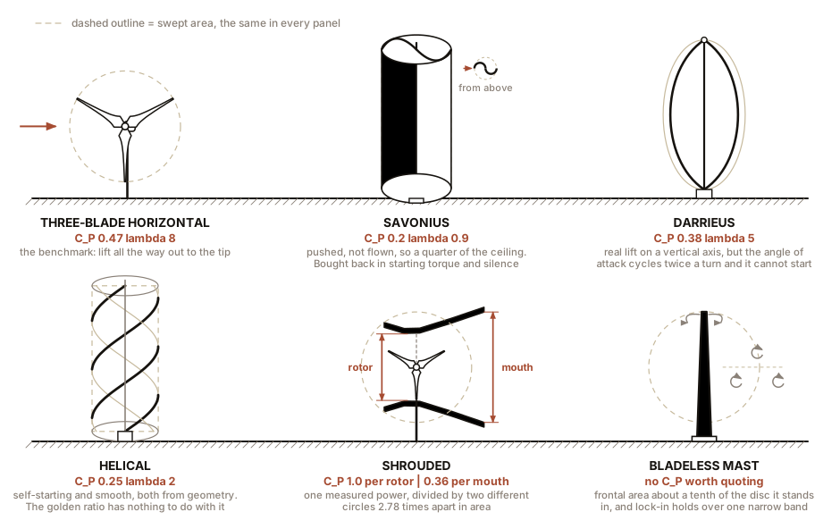
Those are the four machines that turn a shaft, and three of them lost to the benchmark for reasons you could have predicted from Chapter 4 before anybody showed you a test result. The three that remain are the ones sold on the claim that this arithmetic does not apply to them. Chapter 8 takes them in order: the funnel, the mast that does not turn, and the machine with nothing moving in it at all.

Bench Degree
Get the degree without the diploma.
Learn the material, not how to pass the exam.