Bench Degree·WIND POWERchapter
Chapter 8: The Shroud, the Mast, and the Machine With Nothing Moving
One of these three is measured honestly and quoted dishonestly. One is honest and unproven. One produces milliwatts and is the most interesting object in the volume.
Chapter 7’s two rules still hold, and this is the chapter where the second one does all the work. Lift beats drag by a factor of four, and the Betz limit applies to the total frontal area of the device rather than to whichever part of it happens to turn.
The three machines here all appear to escape that. A rotor inside a funnel reports a power coefficient above 0.593 and is not lying about the measurement. A mast that does not rotate at all makes power by swaying. A set of charged wires with nothing moving in them except air makes a voltage out of wind. None of the three beats Betz, all three are worth understanding, and one of them has an argument this book cannot settle.
Section 1: The Shroud, Which Does Not Beat Betz
A rotor inside a flared funnel. The trade name is a diffuser-augmented wind turbine, the sales pitch is that it cheats the wind, and this is the sharpest teaching moment in the chapter because the physics claimed is entirely genuine and the conclusion drawn from it is entirely false.
What actually happens is real. The flared duct downstream of the rotor entrains the outside flow, which lowers the static pressure at the duct’s exit, which lowers the pressure behind the rotor, which draws more air through the rotor than would pass through a bare disc of the same diameter. The mass flow genuinely rises. A small rotor inside a good duct genuinely does produce more than the same rotor in the open. Measured power coefficients referred to the rotor’s own area of 0.7, 0.9, even above 1.0 have been reported, and those are not fraudulent measurements.
They are honest measurements of a dishonest ratio.
Betz’s limit is a limit on the frontal area of the device, because that is the area of moving air the device is interfering with. Chapter 5 Section 1 made the actuator disc an upper bound on any machine precisely by refusing to describe it, so a rotor with a funnel around it is still one machine and the disc that bounds it is the disc that covers the funnel. Referred to the duct’s mouth area, the maximum is still 16/27, and the theoretical work on ducted turbines has said so consistently for decades.
Do the arithmetic once and the miracle disappears.
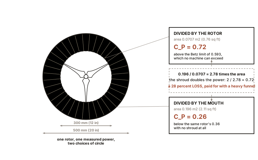
A 300 mm (12 in) rotor has a swept area of 0.0707 square metres (0.76 square feet). Put it inside a shroud whose mouth is 500 mm (20 in) across, and the frontal area is 0.196 square metres (2.11 square feet). The shroud is 2.78 times the area of the rotor.
Now suppose the shroud is excellent and doubles the power. Per rotor area, your power coefficient has doubled and you have apparently beaten Betz. Per shroud mouth area, it is 2 divided by 2.78, which is 0.72 of the bare rotor’s coefficient. You have not gained, you have lost 28 percent, and you have paid for a heavy funnel to do it.
A shroud is a way of buying capture with structure. That is a real trade and sometimes a sensible one, and it is not a free one. A duct that increases capture by a factor of two must be at most 1.41 times the rotor diameter in mouth size to break even, and a duct with a mouth only 41 percent wider than the rotor is not much of a diffuser.
This is why serious attempts keep failing commercially rather than physically. A 7 m (23 ft) diffuser-augmented machine was built in New Zealand in the late 1990s and did not meet projections. A well-funded American venture pursued a shrouded design through the 2010s and did not reach production. The duct is heavy, it must yaw with the rotor, it presents an enormous side area to the wind when yawed, and it costs more than the extra blade it replaces.
Where a shroud is genuinely right is where the constraint is not area. A ducted rotor has no exposed blade, which matters on a roof where children and birds are. It is quieter. It tolerates yaw error better. It can be made to work at low wind speed. Those are real advantages for real situations, and none of them is “more efficient than a bare rotor of the same size”, which is the one thing it is always sold as.
ON THE BENCH: Watch the gain evaporate
Parts: a model rotor of about 300 mm (12 in) diameter on its motor; stiff card or thin plastic sheet to build a shroud with a throat just clearing the rotor and a mouth about 500 mm (20 in) across, flaring downstream over a length of about 400 mm (16 in); a box fan; a multimeter; a fixed load resistor; a tape measure. Cost: a few dollars of card. Time: two hours. Hazards: the fan. A card shroud in a fan stream can take off; tape it down.
Method: 1. Measure the bare rotor’s power into the fixed resistor. Record the rotor diameter. 2. Fit the shroud with the rotor at the throat. Measure again at the same fan setting and the same distance from the fan, measuring distance from the rotor plane and not from the shroud’s lip. 3. Measure the shroud’s mouth diameter. 4. Compute the power coefficient twice, once dividing by
½ρv³times the rotor area, once dividing by½ρv³times the mouth area.What you should see: shrouded output higher than bare, quite possibly by 50 to 100 percent, which is the real effect and it is satisfying to see. And a power coefficient per mouth area that is lower than the bare rotor’s. The gain is in the first column and the loss is in the second, and both numbers are correct.
If it does not work: if the shroud makes no difference, the flare is too short or too abrupt and the flow is separating inside it. A gentle flare over a length comparable to the rotor diameter works better than a steep one. If output falls, the throat is too tight and choking the rotor.
Better, if you have one: an anemometer in the throat will show the speed-up directly, typically 20 to 40 percent, which is genuinely impressive and genuinely does not help as much as it looks.
Section 2: The Mast That Does Not Turn
A slender vertical cylinder, fixed at the base, free at the top, with an alternator of coils and magnets down inside it. Nothing rotates. The wind blows past, the mast sways, and the sway is harvested. A Spanish company, Vortex Bladeless, has been developing this since around 2014.
The mechanism. When air flows past a blunt body, the flow cannot follow the back of it and peels away into a train of vortices, shed alternately from one side and then the other. Each shed vortex pulls the body sideways, so the body is pushed left, right, left, right, at a frequency set by the Strouhal number:
f = St · U / Dwhere St is about 0.2 for a circular cylinder over a very wide range of conditions, U is the wind speed and D is the cylinder’s diameter. For a mast 200 mm (8 in) across in a wind of 5 m/s (11 mph), that is 5 Hz.
If that shedding frequency comes near the structure’s own natural frequency, the two synchronise. This is called lock-in: the shedding stops obeying the Strouhal formula and starts obeying the structure, the motion and the shedding reinforce each other, and the amplitude grows. This is vortex-induced vibration, and running it deliberately, with a tuned mast and a generator, is the whole idea.
One correction, because the popular account of this technology gets a famous example wrong. The Tacoma Narrows bridge collapse of 1940 is almost always described as resonance with vortex shedding. The engineering consensus is that it was torsional flutter, a self-excited aeroelastic instability in which the deck’s own twisting motion generates the force that twists it further. That is a different mechanism from vortex-induced vibration, and it is worth knowing that the analogy runs in the direction that flatters the bladeless mast rather than against it. The mast really does use vortex-induced vibration. The bridge, probably, did not.
The published claims, and they are refreshingly modest. The company states that its machines harvest about 30 percent of the swept-area capture of a three-blade turbine of the same height, at roughly 45 percent lower cost, and that its 2.75 m (9 ft) unit is rated near 100 W. So the claim is explicitly not efficiency. It is cost per watt and packing density: a small swept area means you can stand many masts in a field that would hold one turbine.
That is a legitimate argument and this book will not pretend otherwise. No bearings, no gearbox, no yaw drive, no blade to fatigue, almost no noise, nothing at height to maintain. If cost per kilowatt-hour is the verdict, and Chapter 7 Section 1 said it is, then a device at a third of the capture and half the cost is worth arguing about.
And here is the honest objection, which is one you can now derive and which is not the objection usually made.
The objection usually made is that the capture is low. That is not an objection, it is the design.
The real objection is that lock-in is narrowband, and real wind is not. A mast is a mechanical resonator with one natural frequency. Lock-in holds over a band of wind speeds roughly 25 to 40 percent either side of the tuned speed. Outside that band the shedding and the structure fall out of step and the amplitude, and therefore the power, collapses.
Now bring in Chapter 10’s Weibull distribution, which says a real site’s wind speed is spread broadly across a wide range with no narrow peak anywhere. Compute what a narrowband device can reach.
Take a site with a mean wind speed of 7 m/s (16 mph) and a Weibull shape factor of 2, which is an ordinary temperate onshore site. Now tune a mast to 5 m/s (11 mph), and give it a generous lock-in band from 3.5 to 7 m/s (8 to 16 mph). Integrate the cube of wind speed over that band against the distribution, and against the whole distribution, and you get this:
- The 3.5 to 7 m/s (8 to 16 mph) band contains about 9 percent of the site’s annual wind energy.
- Widen the band as far as 4 to 9 m/s (9 to 20 mph), which is more generous than any published lock-in range, and it contains about 23 percent.
A device that only works inside one band is idle for most of the energy. Not most of the hours, most of the energy, which is worse, because Chapter 10 shows the energy lives in the strong winds and those are exactly the ones outside a low-tuned band.
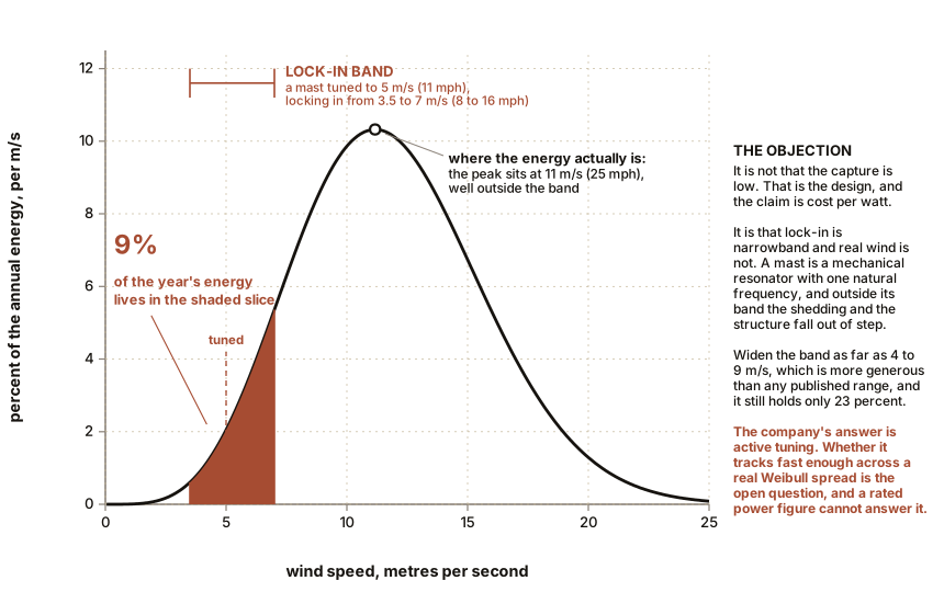
The company’s answer to this is real and it is the crux. Their design uses magnetic confinement to vary the effective stiffness of the mast, and therefore its natural frequency, with amplitude and with wind speed. That is active tuning, tracking the resonance to follow the wind. Whether it tracks fast enough and widely enough across a genuine Weibull spread is the open question, and it is not one that a rated power figure can answer.
Which is the general lesson and the reason this section exists. A rated output is the power at one stated wind speed. It is not annual yield and it is not a capacity factor, and Chapter 16 explains how far apart those things can be. The only thing that would settle the bladeless argument is a measured annual energy yield, taken against a reference met mast to the IEC 61400-12-1 standard, at a site whose distribution is published. Until somebody publishes that, this book gives you the numbers and names the doubt, and declines to pick a side it cannot support.
A second objection, smaller and worth a sentence. An oscillating mast is a fatigue machine by design. It must flex tens of millions of times a year, and Chapter 9’s rule that composite fatigue damage rises as roughly the tenth power of stress range applies to a swaying mast exactly as it applies to a rotating blade. Long service life is claimed and it is not yet demonstrated by a fleet with years on it.
Section 3: The Seventh, Which Nobody Counts
The chapter is called six ways because six things rotate or sway. There is a seventh with no moving parts at all, and it is the strangest and the most beautiful.
In 2013 researchers at Delft University of Technology in the Netherlands built EWICON, an Electrostatic Wind Energy Converter. It has no rotor, no mast that sways, nothing that moves except air.
The mechanism, and it is the point of the whole section. Charged water droplets are released into the wind from an array of nozzles. The array is held at a potential, so there is an electric field pushing back against the droplets’ charge. The wind carries the charged droplets away against that field. Moving a charge against a field is work, the wind does the work, and the work appears as electrical potential energy on the electrode the charge left behind. Wind in, voltage out, with nothing turning.
Richard Epstein’s Solid-State Wind-Energy Transformer does the same thing without water, which removes the obvious problem. The prototype is described as 55 parallel aluminium wires strung between two 8.5 m (28 ft) wooden masts about 8 m (26 ft) apart on a flat roof. Some wires are plain collectors. The others are emitters, carrying small tufts of carbon fibre about 7 µm (0.0003 in) in diameter every 150 mm (6 in). A small negative current on the emitters produces corona discharge at the fibre tips, throwing negative ions into the air. The wind sweeps those ions away from the array and uphill against the field, the array is left positive, and electrons flow in from ground to be collected as current. The process is called electrohydrodynamics.
And now the thing worth carrying out of this chapter. Put voltage into a corona electrode and air moves: that is an ionic wind thruster, and it is a machine from the Plasma volume of this series, recommended if you want it in full. Put moving air into the same electrode and voltage comes out: that is this. Same electrode, same corona, same physics, arrow reversed. It is the clearest example of reversibility anywhere in these volumes, and Chapter 1’s box fan and this converter are the two ends of one machine.
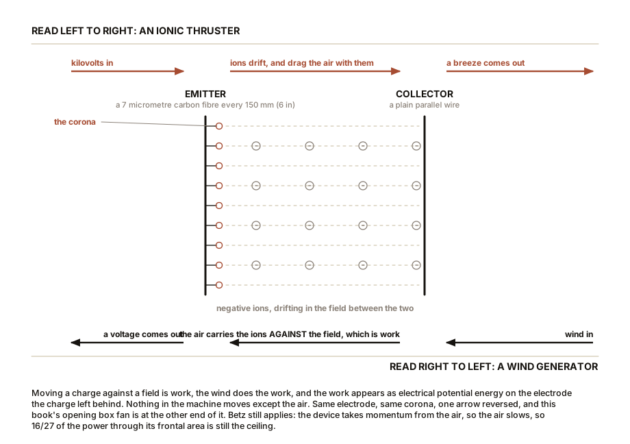
Betz applies here too, and saying so is a good test of whether Chapter 5 landed. The converter takes momentum from the air by dragging charge through it, so the air slows, so 16/27 of the power through the device’s frontal area is still the ceiling. Nothing about the absence of blades changes that.
The practical verdict is not kind. EWICON needed a water supply and would not work below freezing. Epstein’s prototype produced a small fraction of a watt, which is honest for a proof of principle and a long way from useful. And there is a physics bind underneath: corona discharge costs power continuously. It needs kilovolts to initiate and it draws current whether or not the wind is blowing. Net output requires the wind’s work on the drifting charge to exceed the corona’s own consumption plus the leakage, and how much headroom exists there is genuinely unsettled.
Neither approach has reached a competitive cost per kilowatt-hour and neither is close. But a wind machine with no bearings, no gearbox and no blade to fatigue is worth understanding even if nobody has yet made it pay, and understanding it costs you nothing.
The scorecard, then, with the two rules applied.
| Configuration | Type | Peak C_P | λ | What it buys | Betz-honest? |
|---|---|---|---|---|---|
| Three-blade horizontal | Lift | 0.45 to 0.50 | 7 to 9 | the benchmark | yes |
| Savonius | Drag | 0.15 to 0.25 | 0.8 to 1.0 | starting torque, silence, simplicity | yes |
| Darrieus | Lift | 0.35 to 0.40 | 4 to 6 | direction insensitivity, tension-only blade | yes |
| Helical vertical | Lift | 0.20 to 0.30 | 2 to 4 | self-starting, low noise, low vibration | yes, once you ignore the φ claim |
| Shrouded | Lift | 0.7+ per rotor, under 0.593 per mouth | 4 to 6 | no exposed blade, yaw tolerance | only if you quote the mouth area |
| Bladeless mast | Vortex | about 0.30 of a turbine’s capture | none | nothing to wear out, high packing density | yes, and honest about it |
| Electrostatic | Field | measured in milliwatts | none | no moving parts at all | yes |
SLOW DOWN. Check Your Understanding: A vertical-axis turbine is often advertised as better for urban rooftops because “it works in turbulent wind and from any direction”. Both of those statements are true. Given everything in these two chapters and Chapter 1, why is the conclusion still usually wrong? Answer before reading on.
Because the cube law is bigger than both advantages put together.
Chapter 1 established that power goes as the cube of wind speed. Chapter 9 will show that the wind close to a building is not merely turbulent, it is slow, typically 3 to 4 m/s (7 to 9 mph) mean where the wind 30 m (100 ft) up is 6 m/s (13 mph). Halving the wind speed cuts the available power by a factor of eight, and no amount of turbulence tolerance recovers a factor of eight.
So the argument as usually made compares a vertical machine and a horizontal machine at the same bad location, where the vertical machine does indeed win. The comparison that matters is against the same money spent on a taller mast, or on solar panels, and against those the rooftop vertical machine loses badly. Chapter 15 does that arithmetic honestly and it is not close.
The deeper point, and it is the one to keep from this whole chapter: the configuration is almost never the thing that decides the outcome. The site is. Every design in the scorecard above spans a factor of about three in power coefficient. A poor site against a good one spans a factor of eight or more. You can lose more by choosing the wrong roof than you can gain by choosing the right rotor, and every argument about configurations is conducted as though the opposite were true.
Chapter 9 is therefore about the wind rather than the machine, which given the paragraph you have just read is where the money has been all along.

Bench Degree
Get the degree without the diploma.
Learn the material, not how to pass the exam.