Bench Degree·WIND POWERchapter

Chapter 11: Blade, Hub, Drivetrain
A modern wind turbine is a materials achievement wearing an aerodynamic costume. Betz’s number was available from 1919; the blade that makes it worth having arrived in the 1960s and came out of a boatyard.
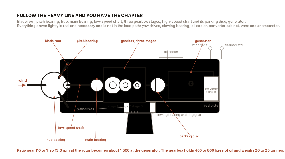
Stand at the base of a 3 MW machine and what you can see is a tube, a box and three blades. Here is what is in them, in the order that load travels: from the tip of a blade, through the hub, along the shaft, through the gearbox, into the generator, down the cable, through the tower and into the ground.
The machine this book uses throughout, so the numbers interlock: rated 3 MW, rotor 110 m (361 ft) in diameter, swept area 9,503 square metres (102,290 square feet), hub height 100 m (328 ft), rated wind speed 10.5 m/s (23 mph), rotor speed at rated 13.6 rpm, tip speed 78.5 m/s (176 mph).
Approximate masses, which are the numbers that decide everything else:
| Component | Mass |
|---|---|
| One blade, 54 m (177 ft) long | 15 tonnes (33,000 lb) |
| Three blades plus hub casting | 65 tonnes (143,000 lb) |
| Nacelle complete, with gearbox and generator | 80 tonnes (176,000 lb) |
| Tower, tubular steel, 100 m (328 ft) | 200 tonnes (441,000 lb) |
| Foundation, concrete and reinforcement | 1,300 tonnes (2,870,000 lb) |
Read the last row against the second. The thing in the ground weighs twenty times the thing that catches the wind. That ratio is what Chapter 12 Section 2 is about.
Section 1: The Blade, Which Is Two Objects Sharing a Skin
Chapter 4 established that the outer two thirds of a blade is a wing and the inner third is a cantilever beam. The construction follows.
The shell is two half-moulds, upper and lower surface, laid up separately and then bonded together along the leading and trailing edges. The material is glass fibre in epoxy or polyester resin, usually infused under vacuum rather than hand laid, because a consistent resin fraction is what fatigue life depends on.
The spar caps are the strength. Two thick bands of unidirectional fibre run the length of the blade, one in the upper shell and one in the lower, and they carry the bending moment exactly as the flanges of an I-beam do. On blades beyond about 60 m (197 ft) these are commonly carbon fibre rather than glass, because carbon’s stiffness per unit mass is roughly twice as good and blade mass is what limits blade length.
The shear webs are one or two internal walls running between the spar caps, making the section a box rather than a shell, and carrying the shear that goes with the bending.
The panels between the webs are a sandwich: thin glass skins either side of a lightweight core of balsa wood or PVC or PET foam. A sandwich resists buckling for very little mass, which matters because a large part of a blade’s skin is in compression on the pressure side and would otherwise dent inward.
The root is a thick cylinder, because a cylinder is what you can bolt. Steel inserts or T-bolts are laminated into the root and take 60 to 120 high-tensile studs into a flange on the pitch bearing. This joint carries the entire blade’s bending moment as a ring of bolt tension, and every one of those studs is tensioned to a specified value and re-checked on a maintenance schedule for twenty years.
And the lightning protection, which is not optional. Metal receptors are set into the blade surface near the tip and at intervals along it, connected by a down conductor of 50 to 100 square millimetres (0.08 to 0.16 square inches) of copper running inside the blade to the hub, and thence through a slip ring or spark gap to the tower and to the earthing system. The international standard for this is IEC 61400-24. Chapter 17 explains what happens when a strike attaches somewhere that is not a receptor, and it is the commonest way blades die.
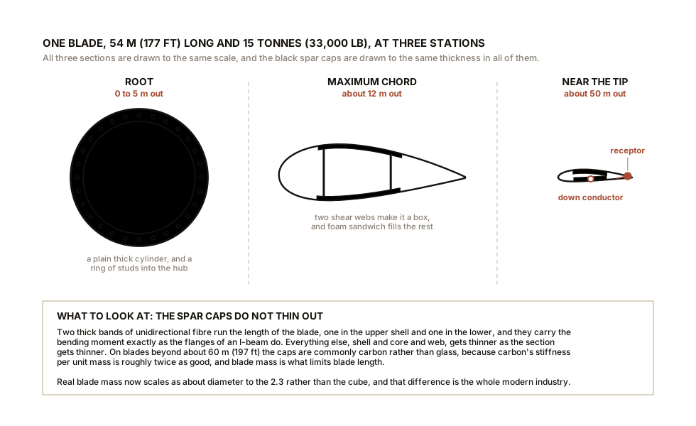
The number that governs blade design is mass, and mass has an unkind scaling. Aerodynamic loads on a rotor scale with swept area, so as the square of diameter. Blade mass, if you simply scaled the design up, would scale as the cube. That mismatch, called the square-cube law, is what would stop rotors growing, and the reason rotors have grown from 15 m (49 ft) in 1980 to over 220 m (722 ft) today is that designers have beaten it: carbon spar caps, better fatigue data allowing thinner sections, aeroelastic tailoring that lets the blade bend usefully instead of resisting, and segmented blades that can be transported. Real blade mass now scales as roughly diameter to the power 2.3 rather than 3.0, and that difference is the whole modern industry.
Section 2: Hub and Pitch, Which Is the Machine’s Only Real Control Surface
The hub is a single casting of spheroidal-graphite cast iron, weighing 15 to 25 tonnes (33,000 to 55,000 lb) on our machine, and it exists to gather three blade roots onto one shaft flange. It is a casting rather than a weldment because the geometry is complicated and the load is fully reversing, and castings tolerate that better than weld toes do.
Inside it are three pitch drives, one per blade. Each turns its blade about its own long axis through a large slewing bearing, and that rotation is the single most important control the machine has. Chapter 14 is about what the pitch system decides. This section is about what it is.
Two technologies, and the choice is not settled:
Electric pitch. A servo motor and a planetary reducer driving a pinion into a ring gear on the pitch bearing. Backed up by a battery or a bank of supercapacitors in the hub, sized to feather all three blades from any position with no external power.
Hydraulic pitch. A cylinder per blade, fed from a pump in the nacelle through a rotary union, with a nitrogen accumulator as the backup store.
Both exist because both answer the same question: what feathers the blades when the grid fails? That is the question, and Chapter 12 Section 1 explains why it is the question. A pitch rate of 5 to 10 degrees per second is typical, so a full 90-degree feather takes 9 to 18 seconds, and the emergency store must be able to deliver that with the nacelle completely dead.
Individual pitch, meaning commanding each of the three blades separately rather than all together, is now common on large machines. It lets the controller reduce the once-per-revolution load that Chapter 9 Section 3 identified, by easing the blade that is at the top of its circle. It buys fatigue life rather than energy, which is a trade this book keeps making, and it is worth it because Chapter 9’s tenth-power rule means a small load reduction buys a large life extension.
Section 3: Gearbox Against Direct Drive, On the Merits
The problem is a mismatch of a factor of about a hundred. The rotor turns at 13.6 rpm. A conventional four-pole generator wants 1,500 rpm on a 50 Hz grid, or 1,800 rpm on 60 Hz. Something has to reconcile those, and there are exactly two ways.
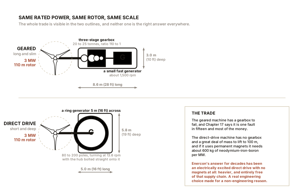
The gearbox. Three stages, typically one planetary set followed by two helical sets, giving a ratio near 110 to 1. It contains 400 to 800 litres (105 to 210 gallons) of oil, a pump, a cooler, a fine filter and a particle counter. It weighs 20 to 25 tonnes (44,000 to 55,000 lb).
The torque it accepts is the number worth remembering: about 2.3 MN·m, which is 1.7 million lb·ft, at rated. That torque is the reason the gearbox exists and also the reason it fails. Chapter 17 shows that the gearbox dominates lifetime maintenance cost.
The direct drive. Delete the gearbox and build a generator that runs at 13.6 rpm. Power is torque times speed, so a generator that turns eighty times slower needs eighty times the torque for the same output, and generator torque scales with rotor volume and with pole count. The result is a ring generator 4 to 6 m (13 to 20 ft) in diameter with 80 to 200 poles, filling the front of the nacelle.
The trade, item by item:
| Geared | Direct drive | |
|---|---|---|
| Drivetrain mass | lower | higher, often much |
| Nacelle diameter | smaller | large ring |
| Parts that wear | gears, bearings, oil, seals | one main bearing |
| Efficiency at low load | falls off | stays high |
| Failure mode | gearbox, and it is expensive | generator, and it is worse |
| Rare-earth magnets | none needed | roughly 600 kg (1,300 lb) per MW if permanent-magnet |
| Field access for repair | components are liftable | often a full nacelle exchange |
Neither wins outright, which is why both are in production after forty years of argument. The pattern that has emerged is that direct drive dominates offshore, where a maintenance visit costs a vessel day and eliminating the highest-failure-rate component is worth almost any mass penalty, while geared machines hold much of the onshore market where a crane can be driven to the site. There are also mid-speed hybrids, a single gear stage of 10 to 30 to 1 driving a medium-speed generator, which is an attempt to take the good half of each.
One honest complication. Permanent-magnet direct-drive machines need neodymium-iron-boron magnets, on the order of 600 kg per MW (1,300 lb per MW), and neodymium and dysprosium supply is concentrated and volatile. Enercon’s answer, for decades, has been an electrically excited direct-drive generator with no permanent magnets at all, which is heavier and uses a little of its own output to make its field and is entirely free of that supply chain. That is a real engineering choice made for a non-engineering reason, and this book notes it rather than pretending the decision was purely technical.
Section 4: The Generator, and Why the Grid Chooses It
Three types are in service, and the choice is dictated more by the grid connection than by the rotor.
The doubly-fed induction generator, or DFIG, dominated the 2000s and is still everywhere. The stator connects directly to the grid. The rotor has windings brought out through slip rings to a power converter, and by injecting a controlled current into the rotor at a slip frequency, the machine can generate at grid frequency while the shaft runs anywhere from about 30 percent below to 30 percent above synchronous speed. The trick is that only the slip power, about 30 percent of the rating, goes through the converter, so the converter is a third of the size and cost of a full one. The price is the slip rings and brushes, which are consumables in an inaccessible place, and a machine that is only partly isolated from grid faults.
The permanent-magnet synchronous generator, or PMSG, with a full-power converter. Everything the machine generates is rectified to direct current and then inverted back to grid frequency. This gives complete freedom of rotor speed, the best low-wind performance, no slip rings, and the ability to ride through grid faults that would trip a DFIG. It costs a converter rated at full power and a quantity of rare-earth magnet.
The electrically excited synchronous generator, as above, with a full converter and a wound field.
And here is the consequence that Chapter 16 will spend a whole section on. In every one of those three, the rotor’s speed is deliberately decoupled from the grid’s frequency, in whole or in part, because that decoupling is what lets the rotor sit at Chapter 6’s optimal tip-speed ratio and harvest the extra energy.
Juul’s Gedser machine of 1957 had no such decoupling and therefore no such harvest, and in exchange it provided grid inertia for free. That trade was made deliberately, by the whole industry, over about fifteen years, and mostly nobody noticed until the grid began to notice. Chapter 16 tells that story.
ON THE BENCH: Take an alternator apart
A 3 MW generator is not available to you. An automotive alternator is, it costs almost nothing, and it contains every principle in Section 4.
Parts: a scrap car alternator from a breaker’s yard or an online auction, $10 to $25; a socket set; a small puller or a bench vice; a multimeter; a variable-speed drill with a suitable socket or a belt and pulley; a 12 V bulb and a 12 V battery. Cost: $15 to $40 all in. Time: two hours. Hazards: wear eye protection when pressing bearings. A spinning alternator on a drill can throw the belt; clamp everything. Do not spin one at drill speed with your fingers near the pulley.
Method: 1. Before opening it, spin it with the drill and measure the output at the B+ terminal with no field current. You will get almost nothing, because the field is not excited. This is the single most useful fact in the teardown. 2. Now feed a small current into the field terminal from the battery through the bulb, spin it again, and watch the output appear. Field current controls output, which is Section 4’s electrically excited machine in your hand. 3. Open it. Identify the three-phase stator winding in the housing, the claw-pole rotor with its single field coil, the two slip rings and brushes feeding that coil, the six-diode rectifier bridge, and the regulator that adjusts field current to hold 14 V. 4. Count the claw poles. Six pairs is common. Frequency is pole pairs times revolutions per second, so twelve poles at 3,000 rpm gives 300 Hz, which is why an alternator is small and a 13.6 rpm generator is enormous.
What you should see: every element of a wind turbine generator, at 1/20,000 of the power. Slip rings, exactly as a doubly-fed machine has. Field control, exactly as an electrically excited direct-drive machine has. A rectifier, exactly as a full-converter machine has. And the pole count and speed argument of Section 3, in a form you can count with a finger.
Better, if you have one: replace the claw-pole rotor with nothing, spin a strong neodymium magnet past the stator by hand, and see voltage appear with no field current at all. That is a permanent-magnet machine, and the fact that it needs no excitation and no slip rings is the whole reason offshore turbines use them.
SLOW DOWN. Check Your Understanding: Blades on the largest offshore machines are now over 115 m (377 ft) long, which is longer than a football pitch, and they are transported in one piece by ship. Onshore, blades much beyond about 70 m (230 ft) are difficult and blades beyond 90 m (295 ft) essentially do not exist. Both use the same materials and the same physics. What is the constraint, and what have manufacturers done about it? Answer before reading on.
The constraint is a corner, and specifically the swept path of a rigid object turning one.
A blade is a rigid beam with no articulation. To get one to an onshore site it must travel by road, which means it must negotiate every roundabout, junction and hairpin between the factory and the crane pad. The limit is not weight and it is not width, it is the geometry of turns, and it is why blade transport uses steerable rear bogies and self-propelled trailers that lift the blade to 60 degrees to swing it over hedges. Beyond about 70 m (230 ft) there are very few routes anywhere that work at any price.
Offshore, the blade goes from a quayside factory onto a ship, and a ship does not turn corners. The constraint simply vanishes, which is most of the reason offshore machines are so much larger than onshore ones, more than any difference in wind or engineering.
What manufacturers have done is worth knowing, because it is a real answer. Some build segmented blades, joined on site with a bolted or bonded spar joint, which solves transport and introduces a fatigue-critical joint in the middle of the most fatigue-critical component, so it is used cautiously. Others have moved production to the site, casting concrete towers and in some cases building blade factories at ports. And the industry’s most common answer is to give up on very long onshore blades and instead raise the tower, because Chapter 9 showed that at inland forested sites height buys more than diameter does.
The general lesson, and it recurs: the binding constraint on a mature technology is very often not in the technology. Tower diameter is set by bridge clearance. Blade length is set by roundabouts. Tip speed is set by planning objections. None of those are in any equation in this book, and all of them decide what gets built.
That is the machine from the blade tip to the high-speed shaft, which is the part that catches the wind and the part that turns it into current. What is left is everything whose job is to point that assembly, hold it up, and stop it, and that is where the mass is. Chapter 12 takes the yaw system, the three brakes, the tower and the concrete.

Bench Degree
Get the degree without the diploma.
Learn the material, not how to pass the exam.