Bench Degree·WIND POWERchapter
Chapter 12: Yaw, Tower, Foundation
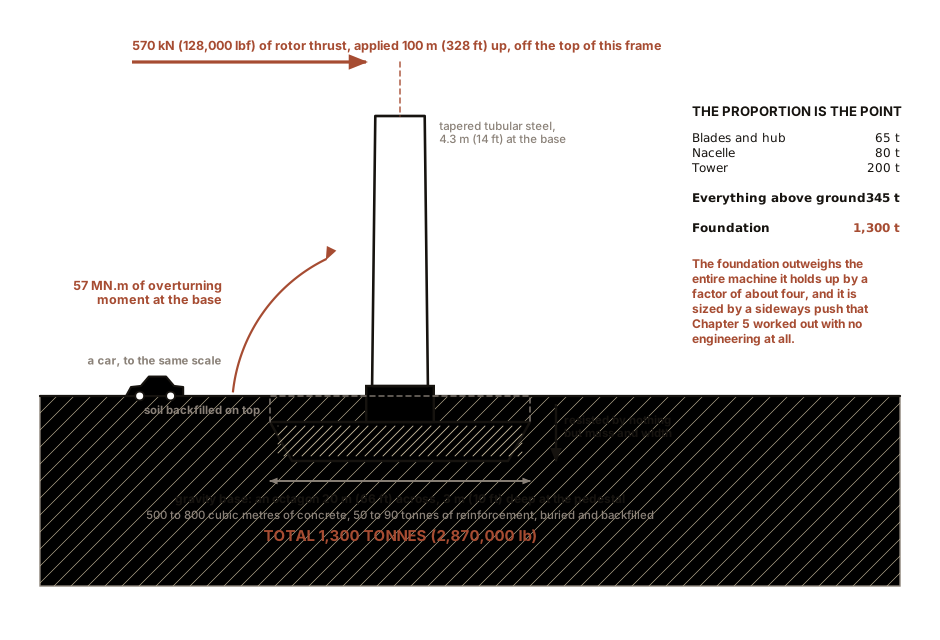
The rotor is in every photograph of a wind turbine. The 1,300 tonnes (2,870,000 lb) of concrete holding it up is in none of them, and it is sized not by the weight above it but by a sideways push that Chapter 5 worked out with no engineering at all.
Chapter 11 followed the load from the tip of a blade to the high-speed shaft. This chapter follows it the rest of the way: out through the yaw bearing, down a steel tube, and into the ground. It also answers the question Chapter 1 promised an answer to, which is what physically stops a wind turbine.
Everything here is a structural problem wearing a mechanical costume. The yaw drive is deliberately slow, because a spinning 65 tonne (143,000 lb) rotor resents being turned quickly. The tower’s diameter is set by stiffness rather than by strength. And the foundation is sized by a steady sideways push of about 570 kN (128,000 lbf) applied 100 m (328 ft) up a tube, which is a far larger problem than the weight of anything.
Section 1: Yaw, and What Actually Stops the Machine
Yaw is the rotation of the whole nacelle about the tower axis, to keep the rotor facing the wind.
On top of the tower is a slewing bearing 3 to 4 m (10 to 13 ft) across with an integral ring gear. Bolted to the bed plate above it are four to ten planetary yaw drives, each a motor and a heavy reduction into a pinion meshing with that ring. On the nacelle roof are a wind vane and an anemometer, and the controller compares the vane’s reading with the nacelle’s heading and calls for a yaw when the error persists.
Three things about yaw that are not obvious:
It is deliberately slow. Typical yaw rate is 0.3 to 0.5 degrees per second, so a 180-degree turn takes six to ten minutes. Yawing fast would apply a gyroscopic moment to a spinning rotor of 65 tonnes (143,000 lb), and gyroscopic loads on the main shaft are exactly the kind of thing that ends a machine.
The brake holds it, the motors do not. Hydraulic brake calipers clamp the yaw ring whenever the machine is not actively yawing. Leaving the load on the gear teeth would chew them.
The cables twist. Power and control cables run from the nacelle down the inside of the tower, and every yaw winds them a little. A counter in the controller tracks accumulated rotation and, after two or three full turns, the machine stops generating and deliberately unwinds itself. That is what a turbine is doing when you see it slowly rotating with its blades feathered on a windy day and nothing coming out.
Now the question every visitor asks, and Chapter 1 promised an answer: what physically stops it?
There are three brakes, and only one of them is what people expect.
The primary brake is aerodynamic, and it is the pitch system. Feathering the blades to about 90 degrees, so their chord lies along the wind, reduces the driving torque to nothing and turns the blades into three long, well-behaved streamlined bodies. A feathered rotor coasts to a stop or idles slowly, and this is how a turbine is stopped, every time, in normal and in emergency conditions. The whole reason Chapter 11 Section 2’s accumulator or battery exists is that feathering must be possible when everything else has failed.
The secondary brake is electromagnetic. The generator and converter can absorb torque on command, and for a controlled shutdown they do part of the work.
The third is a mechanical disc brake on the high-speed shaft, and it is a parking brake. It is there to hold a stopped rotor for maintenance, and to finish the last part of a stop. It is not sized to arrest a rotor turning at rated speed against full aerodynamic torque, and using it that way would destroy it. This is a common misconception, and the correction is worth carrying: a wind turbine is stopped with its blades, not with a brake.
Older stall-regulated machines, which have no pitch system, use tip brakes instead. The outer metre or two of each blade is a separate piece held in line by hydraulic pressure or a latch, and released it rotates 90 degrees and becomes an air brake at the point of maximum leverage. Juul used them at Gedser in 1957 and they work.
IN PLAIN ENGLISH: The blades are the brake. Twisting them edge-on to the wind is like turning a paddle sideways in water: there is suddenly nothing for the wind to push on, and the rotor gives up. The disc brake at the back is for holding the machine still once it has already stopped, the way a parking brake is, and if it were used to stop a running rotor it would catch fire.
Section 2: The Tower, and the Concrete That Nobody Photographs
The tower is a tapered tubular steel cantilever in three to five sections, bolted at flanged joints, each with well over a hundred high-tensile studs. Base diameter about 4.3 m (14 ft) for the transport reason of Chapter 9, tapering to about 2.5 m (8 ft) at the top. Wall thickness from 20 to 50 mm (0.8 to 2.0 in), thickest at the base. Inside are a ladder or a small service lift, a fall-arrest rail, platforms, and the power cables. The step-up transformer sits either at the base inside or in the nacelle.
The tower’s design driver is not strength, it is stiffness. The rotor excites the structure at rotational frequency, called 1P, and at three times that, called 3P, because three blades pass the tower per revolution. Our machine at 13.6 rpm has 1P at 0.23 Hz and 3P at 0.68 Hz. The tower’s first bending mode must be placed clear of both, and the usual choice is a “soft-stiff” design with the tower’s natural frequency between 1P and 3P, which for us means somewhere near 0.3 to 0.45 Hz. Get that wrong and the machine shakes itself apart in ordinary operation.
Then the foundation, and the sentence that surprises people. The load the foundation must resist is not primarily weight. It is the overturning moment from rotor thrust. Chapter 5 computed that thrust at Betz-optimal loading: about 570 kN, or 128,000 lbf, applied 100 m (328 ft) up. That is an overturning moment of about 57 MN·m, or 42 million lb·ft, at the base, in normal operation, and the extreme design case is considerably larger.
Nothing resists that except mass and width. The standard onshore answer is a gravity base: an octagonal reinforced concrete pad 16 to 20 m (52 to 66 ft) across and 2.5 to 3.5 m (8 to 11 ft) deep at the pedestal, holding 500 to 800 cubic metres (17,700 to 28,300 cubic feet) of concrete and 50 to 90 tonnes (110,000 to 198,000 lb) of reinforcement, buried and backfilled. Total mass around 1,300 tonnes (2,870,000 lb), which is the last row of Chapter 11’s opening table.
Alternatives where the ground allows: rock anchors, which post-tension the base into competent bedrock and use a fraction of the concrete, and piled caps where the soil is weak.
How much of the cost is it? Here the outline this book was written from overstated the case slightly, and the honest version is worth having. Onshore, the turbine itself is by far the largest single cost, typically 65 to 75 percent of the installed total, and the foundation is 5 to 12 percent. It is usually the largest civil item, ahead of roads, crane pads and grid connection, and on poor ground it can double and become genuinely dominant. Offshore is where the foundation really does rival the machine: a monopile, its transition piece, the installation vessel and the export cable together can exceed the turbine’s share, which is Chapter 16’s subject.
ON THE BENCH: Find a tower’s natural frequency, and why it must miss two numbers
Section 2 says the tower’s first bending mode has to be placed between 1P and 3P, and that getting it wrong destroys the machine in ordinary operation. That is a resonance argument and it is entirely audible on a bench.
Parts: a length of thin-wall steel or aluminium tube or a steel rule, 600 to 900 mm (24 to 36 in) long; a vice or a G-clamp to hold it vertical at the base; a few large nuts or a lump of modelling clay to serve as a nacelle; a phone with a free audio spectrum analyser application, or a slow-motion video and a stopwatch. Cost: nothing if the tube is in the scrap pile. Time: 40 minutes. Hazards: a clamped tube flicked hard can whip. Keep it away from faces and do not use glass or anything brittle.
Method: 1. Clamp the tube vertically so it stands like a tower, with as little of it gripped as you can manage. 2. Pluck the top sideways and let go. Record the ringing with the spectrum analyser and read off the lowest strong peak. That is the first bending mode. 3. Stick the clay on top as a nacelle and repeat. The frequency will drop. 4. Double the mass on top and repeat again. Note how the frequency falls. 5. Now shorten the free length by clamping higher, and repeat. The frequency will rise sharply.
What you should see: frequency falling roughly as one over the square root of the tip mass, and rising roughly as one over the square of the free length. Both are the standard cantilever result and both are the reason a taller tower needs a wider base.
Then the resonance part, which is the point. Hold a small unbalanced motor against the tube, a hobby motor with a scrap of tape on the shaft will do, and sweep its speed slowly from low to high while watching the top of the tube. At one particular speed the tip amplitude will jump by a large factor for no increase in input. That is your tower meeting its 1P excitation, and on a real machine there is no sweeping past it: the rotor sits at that speed for years.
The design consequence, which you have now felt: our machine’s 1P is 0.23 Hz and its 3P is 0.68 Hz, and the tower’s first mode must live in the gap between them. A tower built too stiff runs into 3P. A tower built too soft runs into 1P. There is a window, and the whole tower design is an argument about staying inside it, which is why tower diameter is not simply a strength calculation.
Chapter 13 takes this hardware and asks what the controller does with it, which is the question the power curve answers.

Bench Degree
Get the degree without the diploma.
Learn the material, not how to pass the exam.